Portable printer

Active Publication Date: 2019-01-10
TOMY CO LTD
View PDF3 Cites 1 Cited by
  • Summary
  • Abstract
  • Description
  • Claims
  • Application Information

AI Technical Summary

Benefits of technology

The present invention addresses existing problems in the related art by providing improvements to existing methods and devices. The technical effects of the invention can significantly enhance the performance of existing technologies.

Problems solved by technology

However, this method cannot be used in a smartphone in which the instant camera function is not available for a user.
After that, the user realizes the error, so that the user feels inconvenience and the printed film is wasted.

Method used


Image

  • Portable printer
  • Portable printer
  • Portable printer

Examples


first embodiment

[0037][Structure of Portable Printer]

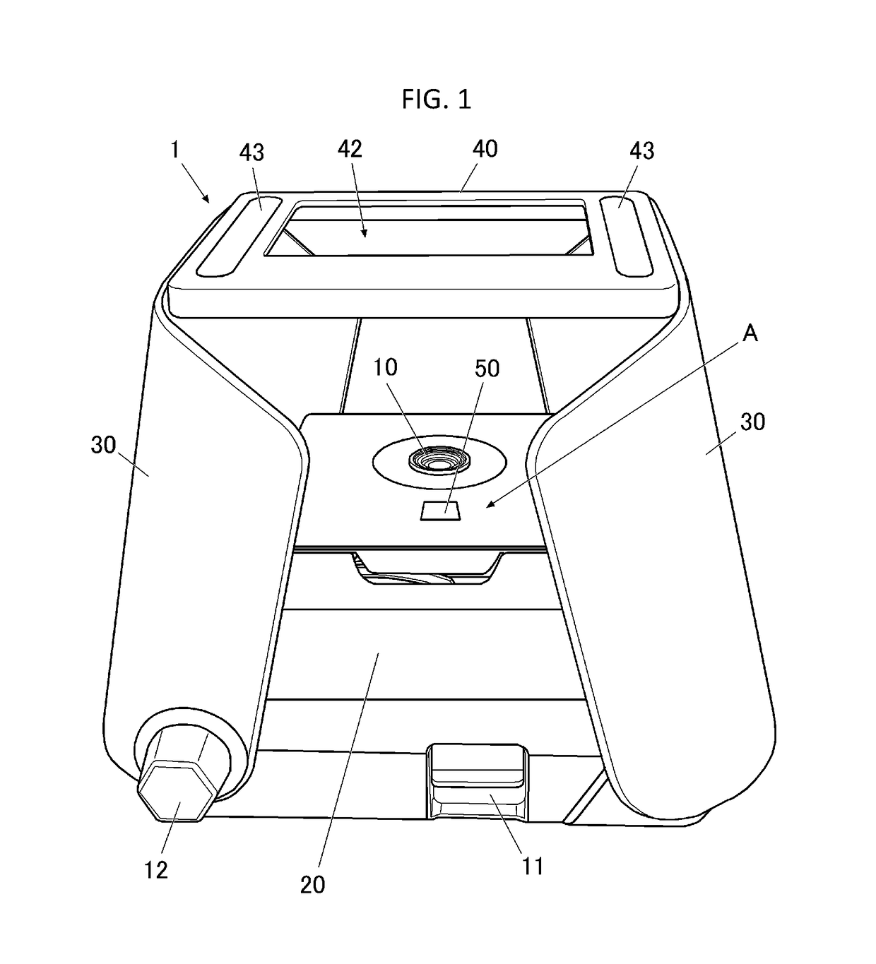
[0038]FIG. 1 is a perspective view showing the configuration of the portable printer according to the first embodiment.

[0039]In the explanation of each part of the portable printer 1, the terms “up”, “down”, “left”, “right”, “front”, and “back” refer to the corresponding directions in FIG. 1. Further, in the present embodiment, as shown in FIG. 1, the portable printer 1 is explained in a case in which the instant camera 10 is integrally installed in the installation part 20. However, it is possible to configure that the instant camera 10 is detachable from the installation part 20 as a separate part between the instant camera 10 and the installation part 20.

[0040]In the present embodiment, a shutter button 11 of the instant camera 10 is provided on the front side of the installation part 20 for operating a shutter function. Further, inside the instant camera 10 (inside the installation part 20), a film pack (not shown) storing a predetermine numb...

second embodiment

[0074][Structure of Portable Printer]

[0075]FIG. 6 is a perspective view showing a configuration of a portable printer according to the second embodiment. FIG. 7 is an illustration showing a multi-stage telescopic arm configuring a part of a supporting part (that is, supporting part 30* in a state after bellows 32 is removed).

[0076]In the explanation of each part of the portable printer 1*, the terms “up”, “down”, “left”, “right”, “front”, and “back” refer to the corresponding directions in FIG. 6. Further, in the present embodiment, it will explain the members having the same configurations or functions described in the first embodiment with the same reference numerals, or the explanation may be omitted. Furthermore, in the present embodiment, as shown in FIG. 6, it will also explain a case in which the instant camera 10 is integrally installed with the installation part 20 in the portable printer 1*, but the instant camera 10 and the installation part 20 may be detachable, so that ...


PUM


Abstract

A portable printer includes a camera, a printing part, a supporting part, and a mirror. The supporting part is configured to support a portable electronic device including a display, in a way in which the display faces the camera with a predetermined distance away from the camera. The support member is configured to cover a space between the portable electronic device and the camera. The mirror is configured to reflect an image on the display and form reflected image thereon. The reflected image on the mirror is viewable by a user. The camera is configured to capture the image on the display. The printing part is configured to print the image captured by the camera.

Description

CROSS-REFERENCE TO RELATED APPLICATIONS[0001]The present application claims priority under 35 U.S.C. 119 to Japanese Patent Application No. 2017-134332, filed on Jul. 10, 2017. The contents of this application are incorporated herein by reference in their entirety.BACKGROUND OF THE INVENTIONField of the Invention[0002]The present invention relates to a portable printer.Description of the Related Art[0003]As a method for printing a film at a spot without bringing a smartphone, etc., which takes an image or sends data, back to a home or a store, for example, there is a portable telephone as described in Japanese Patent Application Publication No. 2001-45342. The smartphone itself may include an instant camera function. However, this method cannot be used in a smartphone in which the instant camera function is not available for a user.[0004]On the other hand, there is a printing method for an electronic camera. As described in Japanese Patent Application Publication No. H11-167161, it ...

Claims


Application Information

Patent Timeline
IPC IPC(8): G03B17/56G03B17/48
CPCG03B17/561H04N5/23248H04N5/2353G03B17/48G03B15/06G03B17/53H04N23/50H04N1/00H04N23/68H04N23/73
Inventor DOHI, MASAHIRO
Owner TOMY CO LTD
Why Eureka
Try Eureka