
Low-frequency electromagnetic tracking

a low-frequency electromagnetic and tracking technology, applied in the field of low-frequency electromagnetic tracking, can solve the problems of affecting the accuracy of medical instruments within the body, affecting the accuracy of medical instruments, so as to facilitate the tracking of the position of medical instruments

Active Publication Date: 2019-01-24
LUCENT MEDICAL SYST
View PDF0 Cites 154 Cited by
  • Summary
  • Abstract
  • Description
  • Claims
  • Application Information

AI Technical Summary

Benefits of technology

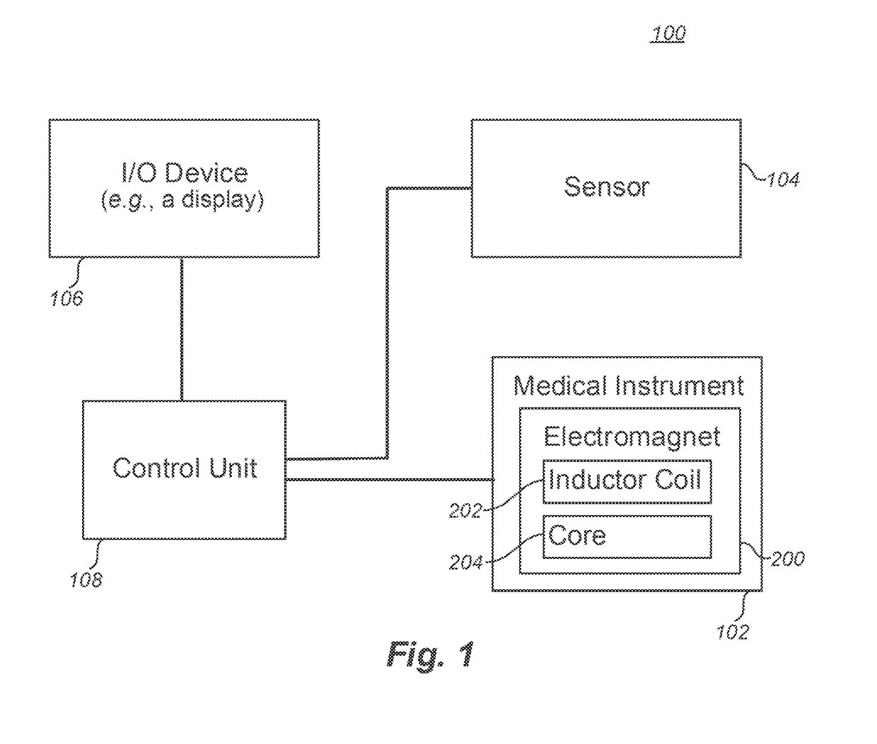
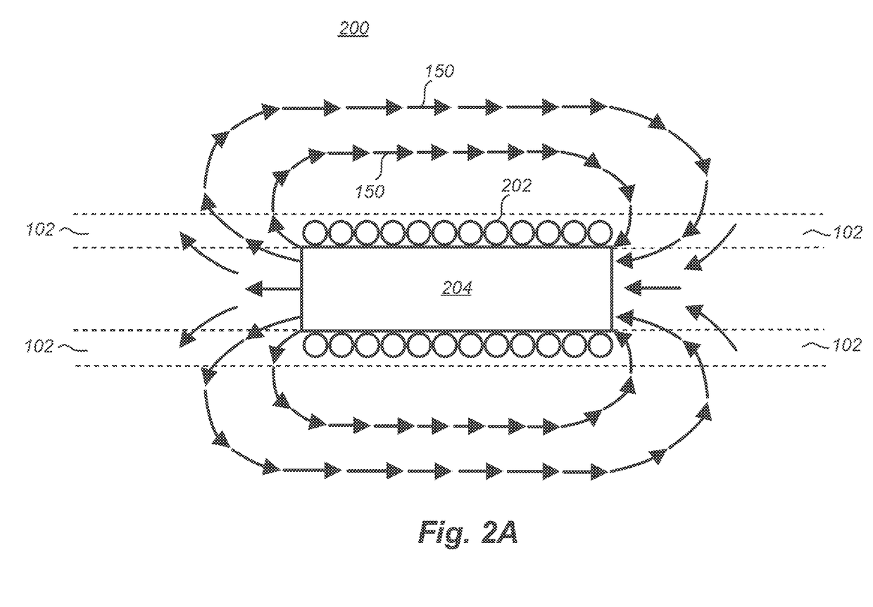
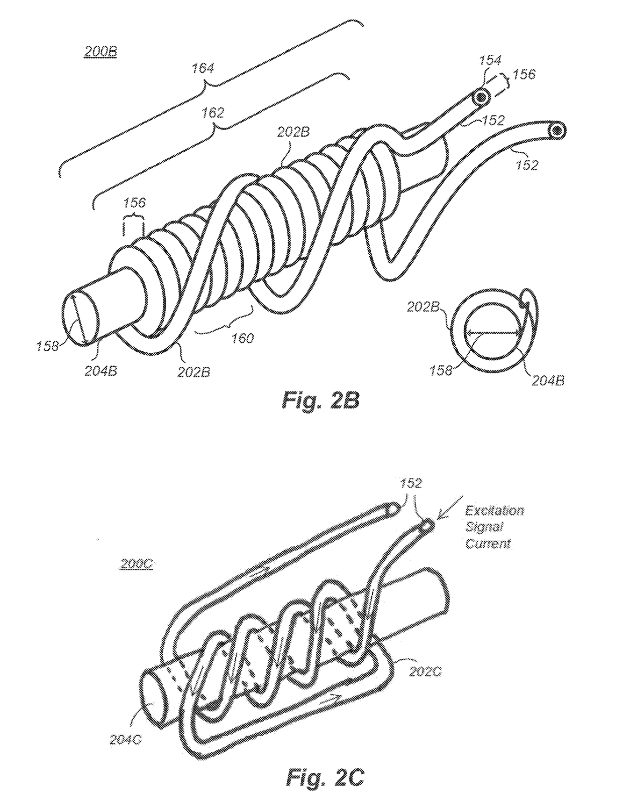
The patent describes a system that uses an electromagnet to track the position of a medical instrument in a patient's body. The electromagnet has a core and an inductor coil. A control circuit passes a current through the inductor coil to generate a magnetic field. A sensor senses the magnetic field and sends a signal to the control circuit, which determines the position, orientation, and motion of the medical instrument based on the sensor signal. The technical effect is a better ability to locate and position medical instruments within a patient's body, allowing for more precise and safe procedures.

Problems solved by technology

Due to the sensitivity of internal tissues of a patient's body, incorrectly positioning the medical instrument within the body can cause great harm.
However, accurately tracking the position of the medical instrument within the body can be quite difficult.
The difficulties are amplified when the medical instrument is placed deep within the body of a large patient.

Method used


Image

  • Low-frequency electromagnetic tracking
  • Low-frequency electromagnetic tracking
  • Low-frequency electromagnetic tracking

Examples


Embodiment Construction

[0051]In the following description, certain specific details are set forth in order to provide a thorough understanding of various disclosed embodiments. However, one skilled in the relevant art will recognize that embodiments may be practiced without one or more of these specific details, or with other methods, components, materials, etc. In other instances, well-known structures associated with computing systems including client and server computing systems, as well as networks have not been shown or described in detail to avoid unnecessarily obscuring descriptions of the embodiments.

[0052]A medical instrument having a new trackable structure is contemplated. The trackable structure includes a low-frequency electromagnetic apparatus that is trackable with a magnetic field sensing device. The magnetic field sensing device includes particular algorithms to identify and track the position of the low-frequency electromagnetic apparatus in three dimensions and the orientation of low-fr...


PUM


Abstract

A medical system tracks the position of a medical instrument within a body of a patient. The medical instrument includes an electromagnet structure having an inductor coil wound around a core. A control circuit applies a low frequency excitation signal across the inductor coil. The inductor coil and the core generate a magnetic field. A plurality of sensors sense parameters of the generated magnetic field and produce sensor signals. The control circuit calculates the position of the medical instrument based on the produced sensor signals.

Description

CROSS-REFERENCE(S) TO RELATED APPLICATION(S)[0001]This application claims the benefit of U.S. Provisional Patent Application No. 62 / 281,155, filed Jan. 20, 2016, and U.S. Provisional Patent Application No. 62 / 344,319, filed Jun. 1, 2016, both of which are hereby incorporated by reference in their entirety.BACKGROUNDTechnical Field[0002]The present disclosure generally relates to tracking an electromagnetic device within a body. More particularly, but not exclusively, the present disclosure relates to tracking, in real time, an electromagnetic device stimulated with a low-frequency when the electromagnetic device is within a body.Description of the Related Art[0003]In many medical procedures, a medical practitioner accesses an internal cavity of a patient using a medical instrument. In some cases, the medical practitioner accesses the internal cavity for diagnostic purposes. In other cases, the practitioner accesses the cavity to provide treatment. In still other cases different ther...

Claims


Application Information

Patent Timeline
Patent Type & Authority Applications(United States)
IPC IPC(8): G01B7/004A61B34/20A61B5/06A61B5/00
CPCG01B7/004A61B34/20A61B5/062A61B5/4836A61B2034/2051A61B2090/378A61B2090/3954A61M2025/0166A61M31/00
Inventor ANDREASON, SAMUEL PETERSANDERS, GARY BRIAN
Owner LUCENT MEDICAL SYST
Learn More