Head-mounted display

a display and head technology, applied in the field of display, can solve problems such as not being entirely satisfactory in all respects, and achieve the effect of convenient donned and removed from the user's head

Active Publication Date: 2019-01-31
QUANTA COMPUTER INC
View PDF1 Cites 16 Cited by
  • Summary
  • Abstract
  • Description
  • Claims
  • Application Information

AI Technical Summary

Benefits of technology

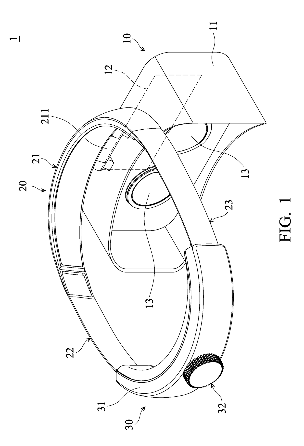
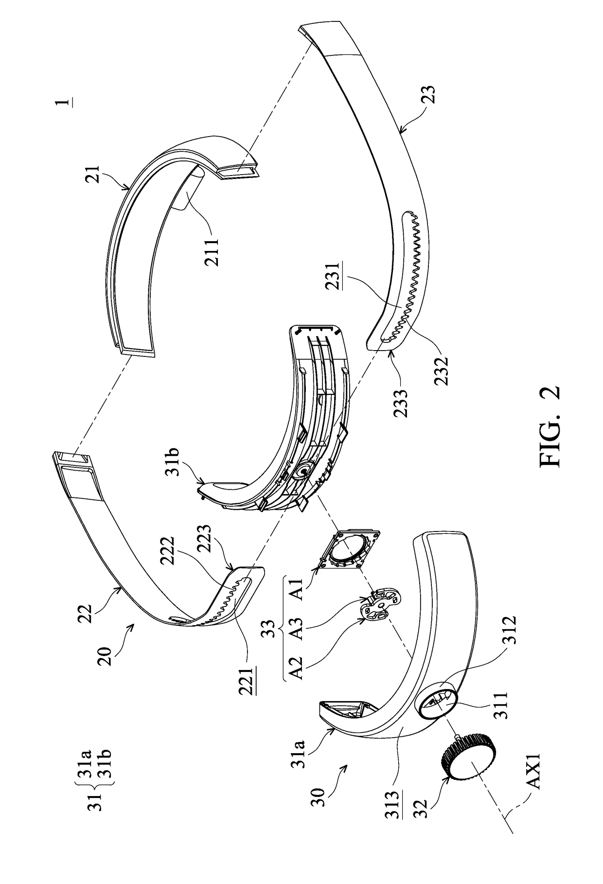
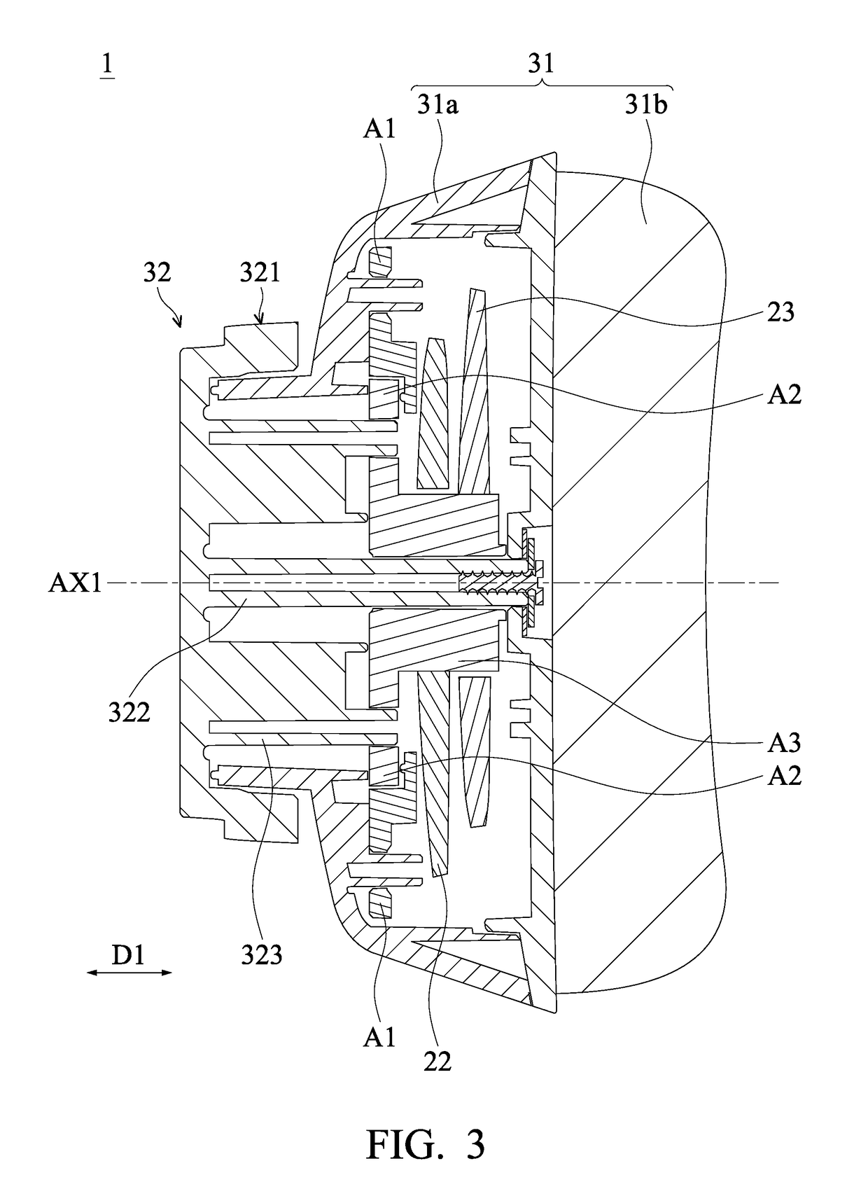
[0008]In conclusion, the user can rotate the rotation button with one hand to change the length or size of the bonding structure, and thus the head-mounted display can be easily donned and removed from the user's head.

Problems solved by technology

Although conventional virtual reality apparatuses have generally been adequate for their intended purposes, they have not been entirely satisfactory in all respects.

Method used


Image

  • Head-mounted display
  • Head-mounted display
  • Head-mounted display

Examples


Embodiment Construction

[0025]The following disclosure provides many different embodiments, or examples, for implementing different features of the present disclosure. Specific examples of components and arrangements are described below to simplify the present disclosure. For example, the formation of a first feature over or on a second feature in the description that follows may include embodiments in which the first and second features are formed in direct contact, and may also include embodiments in which additional features may be formed between the first and second features, such that the first and second features may not be in direct contact.

[0026]Spatially relative terms, such as upper and lower, may be used herein for ease of description to describe one element or feature's relationship to another element(s) or feature(s) as illustrated in the figures. The spatially relative terms are intended to encompass different orientations of the device in use or operation in addition to the orientation depic...


PUM


Abstract

A head-mounted display includes a display device, a bonding structure connected to the display device, an adjusting mechanism connected to the bonding structure, and a rotation button connected to the adjusting mechanism. When the rotation button is rotated, the length of the bonding structure is changed by the adjusting mechanism.

Description

CROSS-REFERENCE TO RELATED APPLICATIONS[0001]This Application claims priority of Taiwan Patent Application No. 106124873 filed on Jul. 25, 2017, the entirety of which is incorporated by reference herein.BACKGROUND OF THE INVENTIONField of the Invention[0002]The present disclosure relates to a display, and in particular to a head-mounted display.Description of the Related Art[0003]A conventional virtual reality apparatus is configured to be worn on the user's head, and to provide 3D (three dimensional) images to the user.[0004]In general, a conventional virtual reality apparatus includes a display panel, and two lenses that correspond to the user's two eyes. The display panel is configured to display a left-eye image and a right-eye image, respectively entering through the left eye and the right eye via the lenses, and a 3D image is presented by the left-eye image and the right-eye image.[0005]Although conventional virtual reality apparatuses have generally been adequate for their in...

Claims


Application Information

Patent Timeline
Patent Type & Authority Applications(United States)
IPC IPC(8): H05K5/02H05K5/00
CPCH04N13/344H05K5/0217H04N2213/001H04N2213/008H05K5/0017G02B27/0176G02B7/002
Inventor CHEN, CHUN-LUNGSUNG, CHIEN-HSIEN
Owner QUANTA COMPUTER INC
Why Eureka
Try Eureka