A well tractor drive section with pairs of drive arm bearings mutually oppositely displaced from the centre line

Active Publication Date: 2019-02-14
C6 TECH
View PDF5 Cites 3 Cited by
  • Summary
  • Abstract
  • Description
  • Claims
  • Application Information

AI Technical Summary

Benefits of technology

[0043]In an embodiment of the invention, the first and second wheel arms (12A, 12B) are designed identically and mounted from opposite directions onto the central structural block (02), please see FIG. 3b. Thus only one type of wheel arms needs be manufactured which reduces maintenance costs and the number of replacement parts required during an operation.
[0044]In a preferred embodiment of the invention the actuator rod is arranged sliding in a bearing (30Ac, 30Bc) in the angular gear housing (2) to force the translation to occur along a fixed line for each rod. A link element (33A, 33B) is arranged between moment arm (32A, 32B) and the end of actuator rod (30A, 30B). With the geometry described above and illustra

Problems solved by technology

This reduces the available space for the cogged wheel and also the available space for displacing the actuator rods while still fitting into a cylindrical pressure housing.
The length of the tool contributes to the overall length of the tractor which thus limits the amount of tractor-borne tools to enter the well through the lock chamber.
Further, w

Method used


Image

  • A well tractor drive section with pairs of drive arm bearings mutually oppositely displaced from the centre line
  • A well tractor drive section with pairs of drive arm bearings mutually oppositely displaced from the centre line
  • A well tractor drive section with pairs of drive arm bearings mutually oppositely displaced from the centre line

Examples


Example

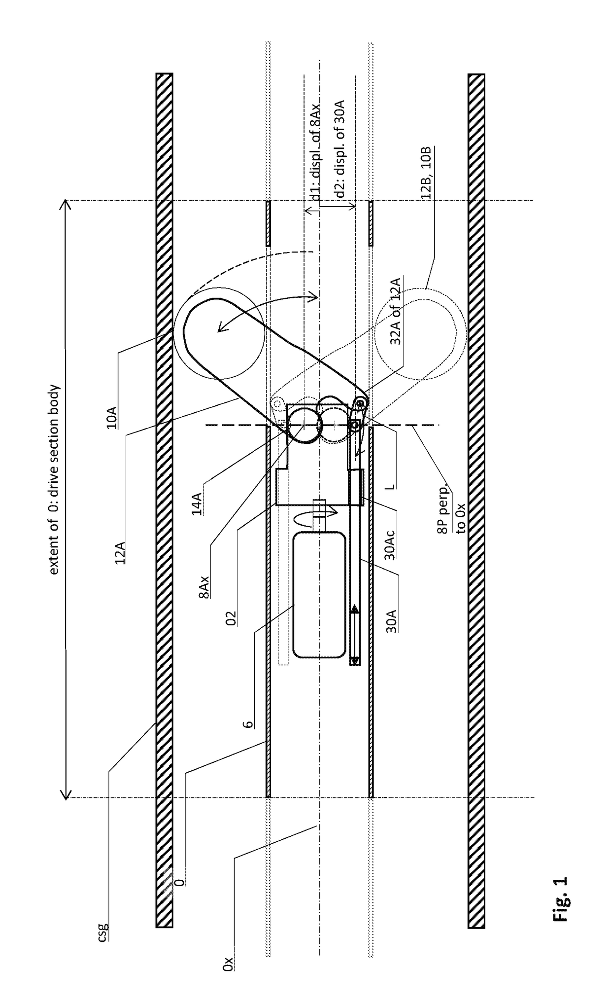
[0014]The invention is a well tractor drive section wherein the wheel arm bearings are in mutually oppositely displaced positions with regard to the main axis, and with corresponding actuator rods which are also in mutually oppositely displaced positions, please see FIG. 1. The two arms are arranged in slots in the drive section body. The two arms fold in and out in the downhole direction as a safety precaution in order to enable the tractor to be pulled out in a passive state from the well if necessary.

[0015]More specifically, the invention is a well tractor drive section comprising the following main features, please see FIG. 1.[0016]The drive section has a drive section body (0) with a main central axis (0x):[0017]The drive section body (0) is provided with first and second drive wheels (10A, 10B) arranged on the ends of first and second wheel arms (12A, 12B), respectively. The drive wheels are arranged for running along an inner bore of a well. The inner bore may be a production...


PUM


Abstract

A well tractor drive section comprising—a drive section body (0) with main central axis (0x), with—first and second drive wheels (10A, 10B) on the outer ends of first and second wheel arms (12A, 12B); inner ends of said wheel arms (12A, 12B) arranged pivotally about first and second transverse axes (8Ax, 8Bx) in first and second transverse-axial wheel arm bearings (14A, 4B) for said wheel arms (12A, 12B) to rotate in a direction away from said main axis (0x) to engage said drive wheels (10A, 10B) with an inner wall of a well; said first and second transverse-axes (8Ax, 8Bx) being mutually oppositely laterally displaced with a first separation (d1) from said main central axis (0x) in a common perpendicular plane (8P) relative to said main central axis (0x).

Description

INTRODUCTION[0001]The invention is a well tractor drive section wherein one of the features is that the wheel arm bearings are in mutually oppositely displaced positions with regard to the main axis. In an advantageous embodiment corresponding actuator rods or so-called push rods are also in mutually oppositely displaced positions, please see FIG. 1. Given an otherwise limited axial push force from an actuator, this feature of opposite separation of the bearing and the actuator rod for each arm provides an increased mechanical advantage of the arm, and thus an increased force of the drive wheels against the wall of the well.PRIOR ART AND PROBLEMS RELATED THERETO[0002]The applicant has a U.S. Pat. No. 326,593 filed Jan. 23, 2007; “Arrangement of wheel driven transport device for moving forward a tool in boreholes and pipelines” wherein single oppositely directed drive wheel arms are distributed along a drive section body of a downhole tool. The arms are actuated by pairs of cogged ro...

Claims


Application Information

Patent Timeline
IPC IPC(8): F16H1/22E21B23/00F16H1/00
CPCF16H1/222E21B23/00F16H1/006E21B2023/008E21B23/14E21B23/001
Inventor ARMSTRONG, KENNY
Owner C6 TECH
Why Eureka
Try Eureka