
Hose joint clamp

Inactive Publication Date: 2010-12-09
AN KOOK IND CO LTD
View PDF9 Cites 1 Cited by
  • Summary
  • Abstract
  • Description
  • Claims
  • Application Information

AI Technical Summary

Benefits of technology

[0024]According to the present invention, a hose fastening clamp is advantageous in that a high clamping force can be obtained without damaging an outer covering of a hose when neighboring hoses are connected to each other, and a clamping force is continuously retained even when a lengthy period of time has passed after the fastening operation was performed so that watertightness and airtightness are maintained, thus reducing maintenance costs, and object

Problems solved by technology

However, the fastening clamp is problematic in that it may be easily loosened by the expansion of the hose when the flow rate and pressure of the objects are high.
The fastening clamp compressing the joint between neighboring hoses is loosened, thus frequently resulting in the leakage of objects from the hoses.
Such a conventional fastening clamp is problematic in that it is impossible to perform a clamping operation in the state where the thickness of the outer covering of the hose is kept constant, so that a clamping force is gradually reduced because the outer covering of the hose is restored to its original state when a lengthy pe

Method used


Image

  • Hose joint clamp
  • Hose joint clamp
  • Hose joint clamp

Examples


Example

DESCRIPTION OF REFERENCE CHARACTERS OF IMPORTANT PARTS

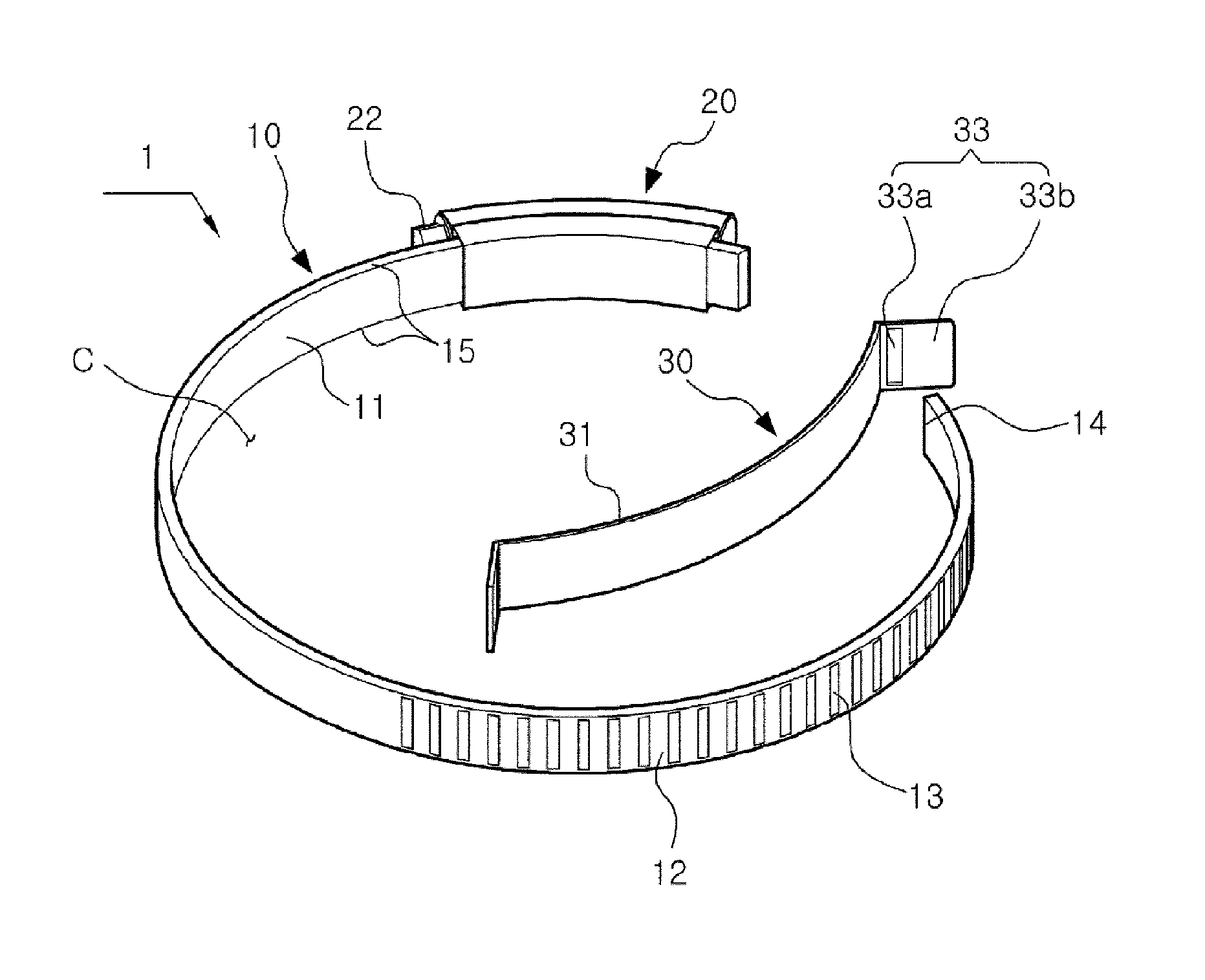
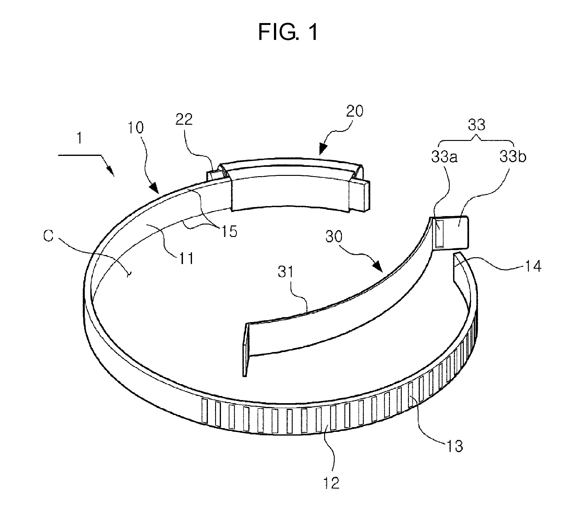
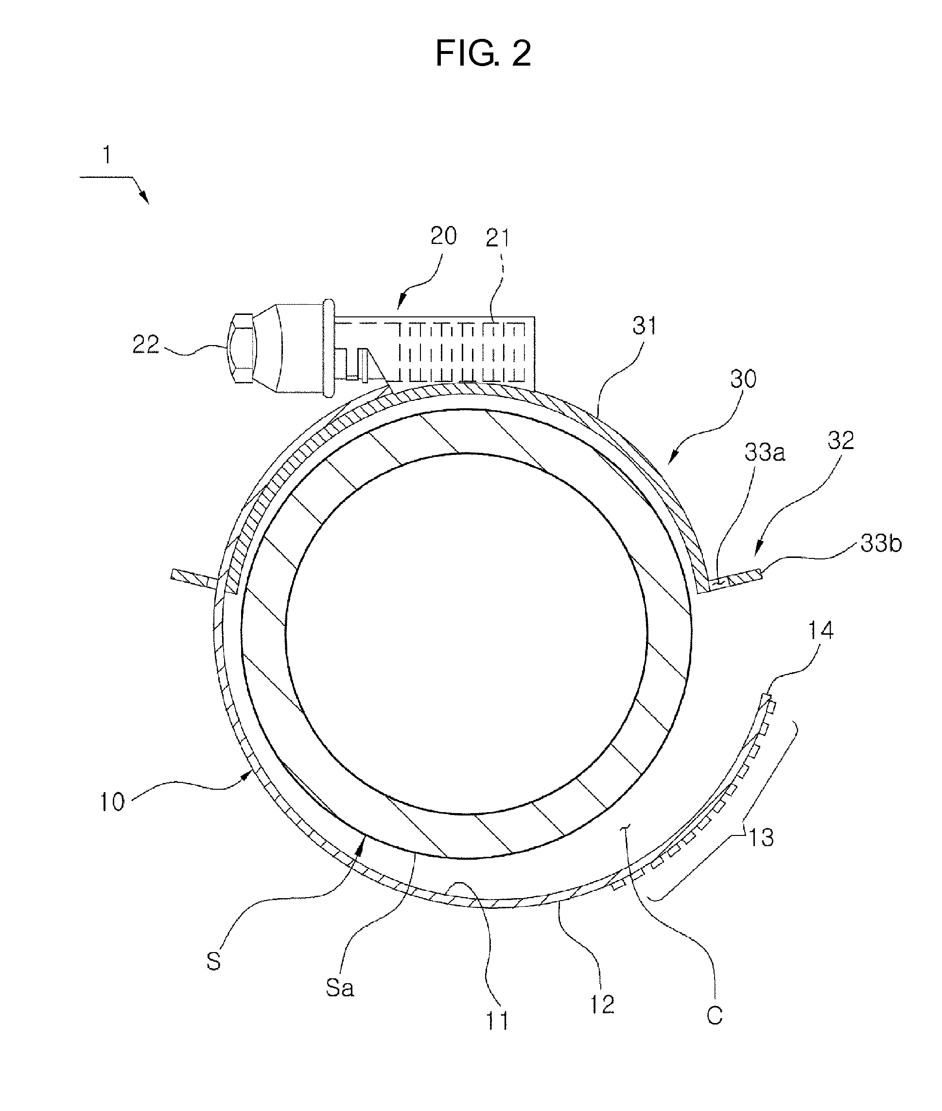
[0034]1: clamp S: hose Sa: outer covering[0035]Sp: overlapping portion J: clamping direction[0036]C: open ring[0037]10: band 11: inner surface 12: outer surface[0038]13: fastening screw unit 14: end 15: right and left edges[0039]20: fastening screw 21: corresponding threads 22: screwhead[0040]30: clamping member 31: body 32: coupling unit[0041]33: first coupling unit[0042]33a: insertion hole 33b: locking part[0043]34: second coupling unit 35: slotted part 35a: slot

BEST MODE

[0044]Hereinafter, the hose fastening clamp according to the preferred embodiment of the present invention will be described with reference to the accompanying drawings.

[0045]When describing the hose fastening clamp according to the present invention, the reference of direction will be specified with reference to FIG. 1.

[0046]In the state in which a band is inserted into a fastening screw and thus an open ring is formed in a predetermined size, a threaded side...


PUM


Abstract

Disclosed herein is a hose fastening clamp used to hold hoses that are connected by various pipe connectors in such a way as to be butted to each other, in addition to maintaining airtightness. The hose fastening clamp prevents an outer covering of a hose that is in contact with a band from being pushed in the rotating direction of the band, and increases a clamping force using the band fastened to the hose. The hose fastening clamp includes a band having on its outer surface a thread and forming an open ring that surrounds a hose. A fastening screw engages with the thread to adjust the diameter of the open ring. A clamping member is placed to be in contact with the inner surface of the band. The diameter of the clamping member is changed in conjunction with a change in diameter of the open ring.

Description

TECHNICAL FIELD[0001]The present invention relates, in general, to a hose fastening clamp which is used to hold hoses that are connected by various pipe connectors in such a way as to be butted to each other, in addition to maintaining airtightness and, more particularly, to a hose fastening clamp, which prevents an outer covering of a hose that is in contact with a band from being pushed in the rotating direction of the band, and increases a clamping force using the band fastened to the hose.BACKGROUND ART[0002]Hoses which have been used in a variety of fields are manufactured to have various shapes with various materials according to the quality of the material, the thermal treatment method, the purpose of use, and the place of installation. Since the hoses are inexpensive and convenient to install, the use of hoses is gradually increasing.[0003]The hose is bent or curved according to the place where it is to be installed, and is butted to an adjacent hose. A fastening clamp is pr...

Claims


Application Information

Patent Timeline
IPC IPC(8): F16L33/02B65D63/00
CPCF16L33/08Y10T24/1439F16L21/06F16L33/02
Inventor AN, BYUNG MOO
Owner AN KOOK IND CO LTD
Learn More