Structure of Sextant Rotary Disk

Active Publication Date: 2016-03-31
HUANG YUNG CHIU
View PDF8 Cites 2 Cited by
  • Summary
  • Abstract
  • Description
  • Claims
  • Application Information

AI Technical Summary

Benefits of technology

[0005]An object of the present invention is to improve the problem of being ready to deform and thus shortening of the lifespan.
[0006]Another object of the present invention is to reduce the maintenance cost.
[0007]A further object of the present invention is to allow for easy separation of an insertion element and a rotary shaft after use.
[0008]To achieve the objects, the present invention comprises a rotary disk, which comprises a plurality of circumferentially distributed mounting slots formed therein. The mounting slots respectively receive retention plates therein. The retention plates each have sides in which retention grooves are formed. The rotary disk receives a plurality of fastening elements to extend therethrough to be respectively fixed to the retention plates. Arranged between the mounting slots and the retention grooves are support members that project outside the rotary disk. The fastening elements induce a stretching force that is applied to the retention plates so that the retention plates apply forces to the support members for fixing. The rotary disk is provided, at a center thereof, with a connection module. The connection module comprises an insertion element. The insertion element has an end in which a conic insertion hole in the form of a convergent configuration is formed. The conic insertion hole receives a rotary shaft to insert therein. An end of the rotary shaft that is

Problems solved by technology

Also, since the bolts are screwed to the circular disk 91, a stretching force is induced, which leads to ready deformation and shortening of the lifespan of the circuit disk 91 during the operation thereof.
Further, the circular disk 91 must be entirely replaced in repairing

Method used


Image

  • Structure of Sextant Rotary Disk
  • Structure of Sextant Rotary Disk
  • Structure of Sextant Rotary Disk

Examples


Example

[0026]The following descriptions are exemplary embodiments only, and are not intended to limit the scope, applicability or configuration of the invention in any way. Rather, the following description provides a convenient illustration for implementing exemplary embodiments of the invention. Various changes to the described embodiments may be made in the function and arrangement of the elements described without departing from the scope of the invention as set forth in the appended claims.

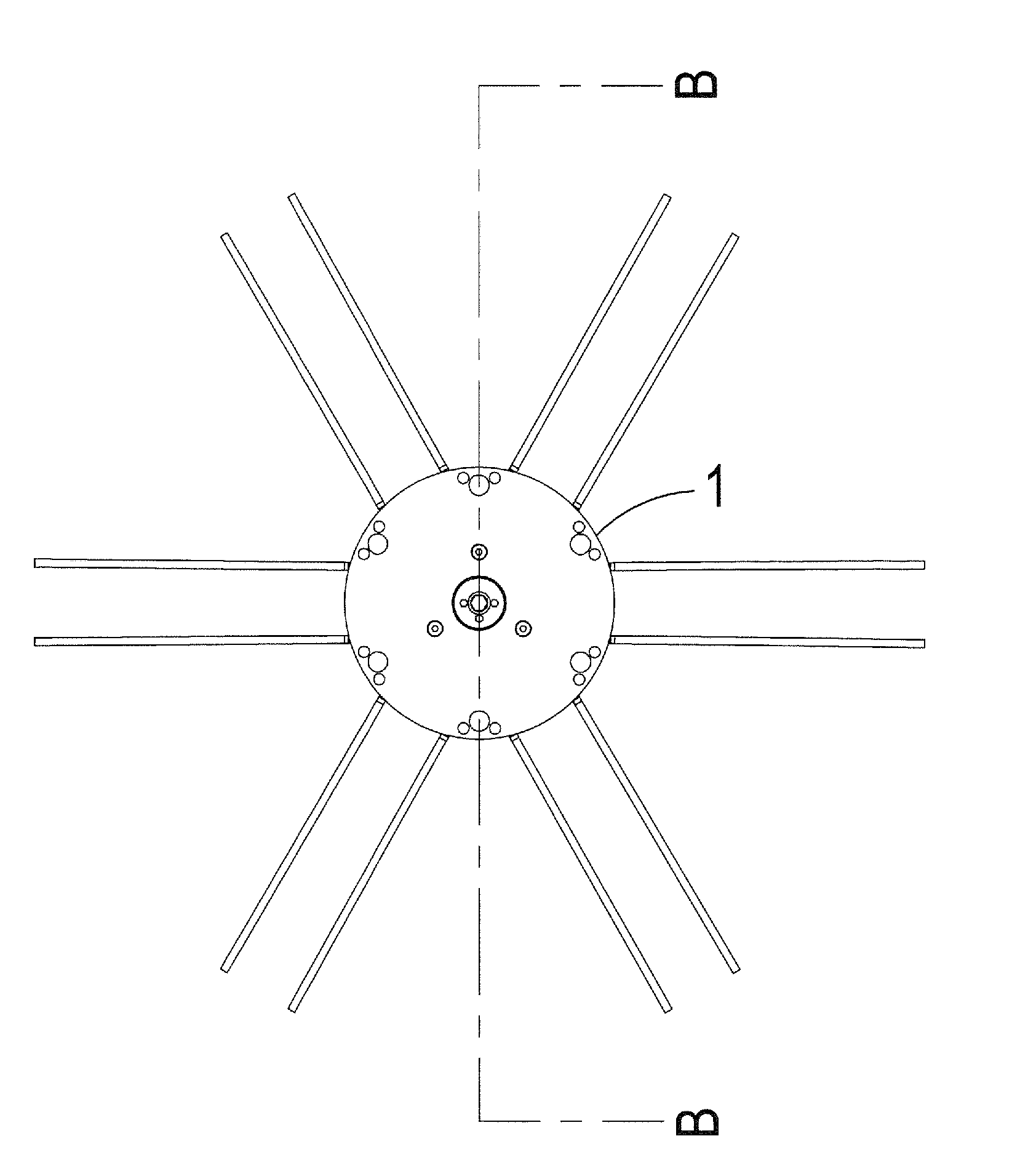
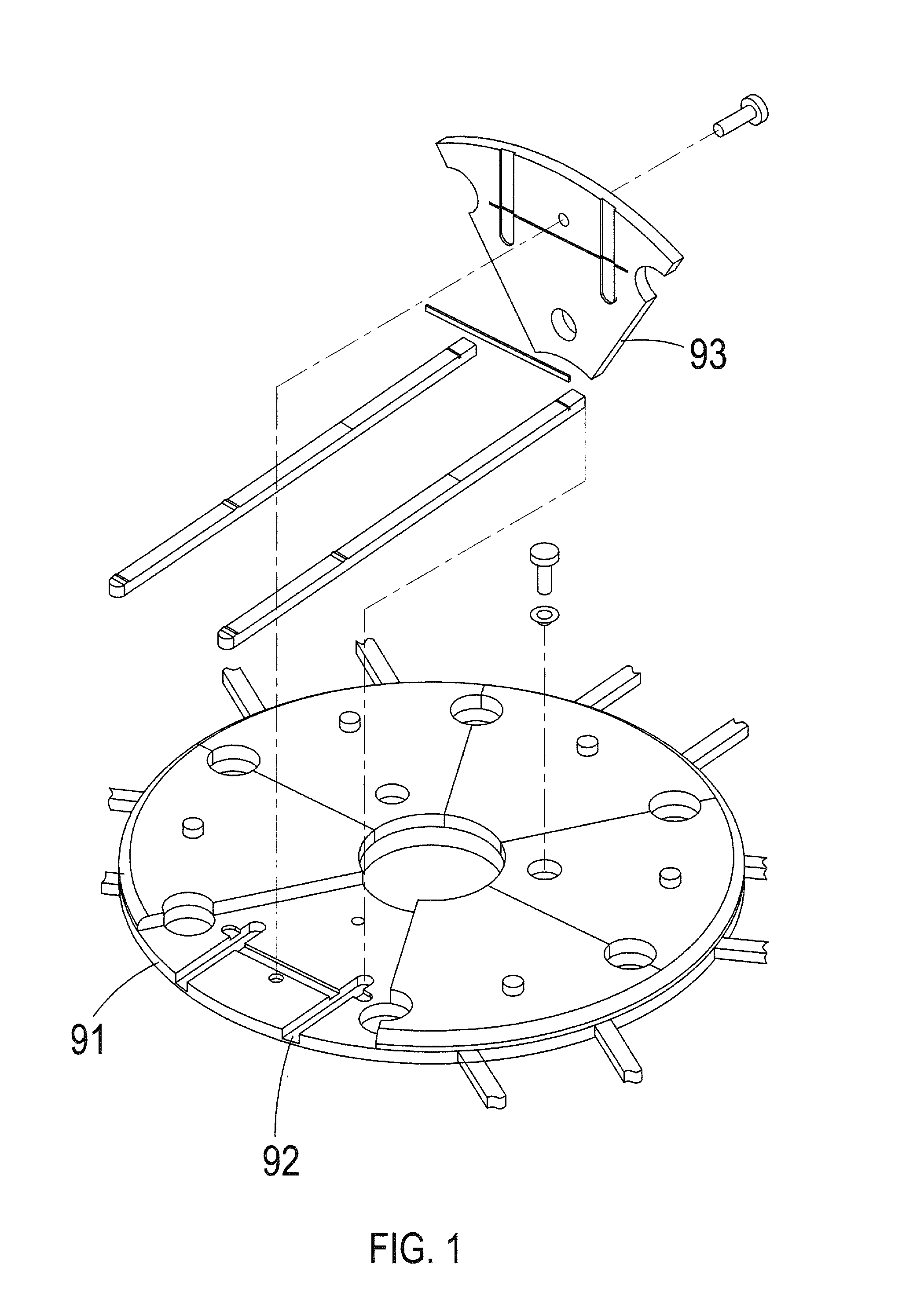
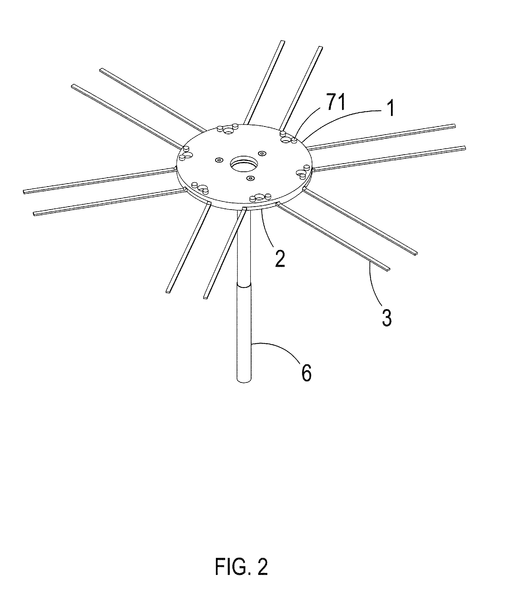
[0027]Referring to FIGS. 2-8, the present invention comprises a rotary disk 1, a plurality of retention plates 2, a plurality of constraint elements 4, a plurality of support members 3, a plurality of fastening elements 71, a connection module 5, and a rotary shaft 6. The rotary disk 1 comprises a plurality of mounting slots 11 formed therein and distributed circumferentially. The retention plates 2 are respectively received in the mounting slots 11 and each has sides corresponding to side walls of ...


PUM

PropertyMeasurementUnit
Thicknessaaaaaaaaaa
Strengthaaaaaaaaaa

Abstract

A sextant rotary disk structure includes a rotary disk in which circumferentially distributed mounting slots are formed, the retention plates received in the mounting slots and having sides forming retention grooves, support members arranged between the mounting slots and the retention grooves, fastening elements extending through the rotary disk and the retention plates for fixing, an insertion element arranged at a center of the rotary disk and having a conic insertion hole in a convergent configuration, and a rotary shaft having an end forming an insertion cone insertable into the conic insertion hole. The thickness of the rotary disk can be increased to improve the strength thereof. Maintenance can be performed by only replacing deformed ones of the retention plates. The arrangement of the conic insertion hole and the insertion cone prevents undesired sticking.

Description

(a) TECHNICAL FIELD OF THE INVENTION[0001]The present invention generally relates to a rotary disk, and more particularly to a structure of a sextant rotary disk that allows for reduction of deformation for extension of lifespan, has a reduced maintenance cost, and is easy to disassemble after use.(b) DESCRIPTION OF THE PRIOR ART[0002]Taiwan Utility Model M296470 discloses a support rotary disk module for wafers, which illustrates a conventional support rotary disk module as shown in FIG. 1, comprising a circular disk 91 having a surface in which at least two grooves 92 are formed, the grooves 92 being arranged to space from each other in a circumferential direction of the circular disk 91 with first fitting sections formed on opposite sides thereof; at least two insertion members, which each have an end comprising second fitting sections formed on opposite sides thereof and are respectively insertable into the grooves 92 with the first fitting sections respectively fit to the secon...

Claims


Application Information

Patent Timeline
IPC IPC(8): F16C11/04
CPCF16C11/04B23Q1/25F16D1/06F16D1/076F16D1/092H01L21/68H01L21/68785H01L21/68792Y10T403/34C23C16/4584H01L21/68771
Inventor HUANG, YUNG-CHIU
Owner HUANG YUNG CHIU
Why Eureka
Try Eureka