Gas Pipe Joint

Active Publication Date: 2021-04-22
GREATNESS SANITARY IND
View PDF0 Cites 1 Cited by
  • Summary
  • Abstract
  • Description
  • Claims
  • Application Information

AI Technical Summary

Benefits of technology

[0007]The primary aspect of the present invention is to provide a gas pipe joint which contains a connection pipe, a first threaded pipe, and a second threaded pipe, wherein the two first loops are mounted on the first threaded pipe and the first groove of the connection pipe, and two second loops are fixed on the connection pipe and the first groove of the second threaded pipe so as to connect the gas pipe joint easily.
[0008]Another aspect of the present invention is to provide a gas pipe joint which contains a connection pipe, a first threaded pipe, a second threaded pipe, a first sleeve, and a second sleeve, wherein the connection pipe is a two-way pipe and includes a first outer screwing

Problems solved by technology

However, the gas pipe joint has two parts in which a right angle or a non-right angle is defined, thus limiting the gas pipe joint.
For example, when moving a heater, the gas pipe joint and a plasti

Method used


Image

  • Gas Pipe Joint
  • Gas Pipe Joint
  • Gas Pipe Joint

Examples


first embodiment

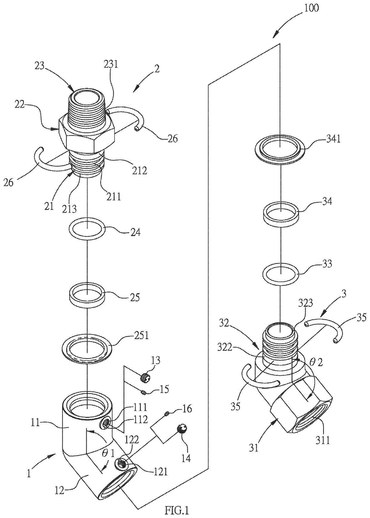
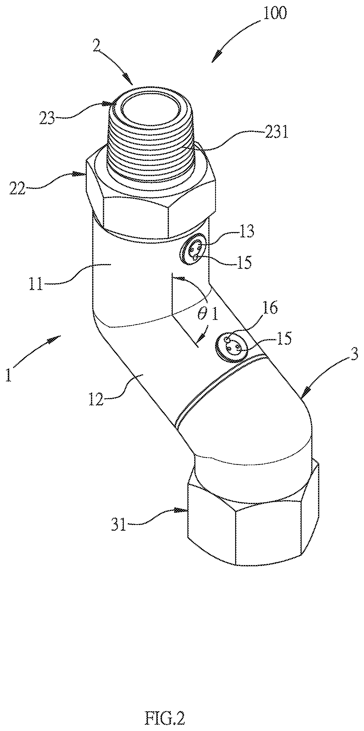
[0015]With reference to FIGS. 1-3, a gas pipe joint 100 according to the present invention comprises: a connection pipe 1, a first threaded pipe 2, and a second threaded pipe 3.

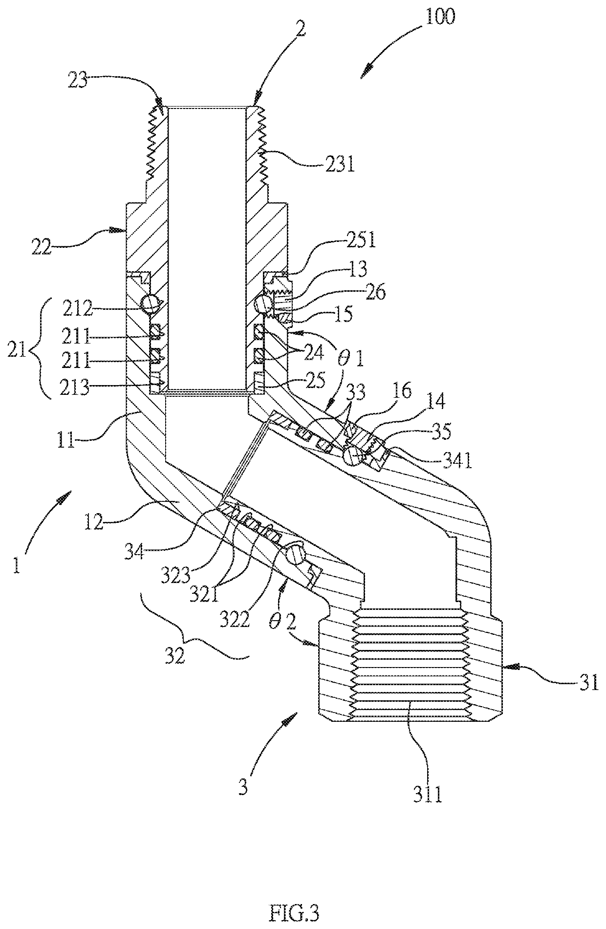
[0016]The connection pipe 1 includes a first part 11 and a second part 12 communicating with the first part 11, and a first angle θ1 is defined between the first part 11 and the second part 12, wherein the first angle θ1 is an obtuse angle. The first part 11 has a first threaded orifice 111 defined on a side surface of the first part 1 adjacent to the second part 12, the second part 12 has a second threaded orifice 121 formed on a side surface of the second part 12 proximate to the first part 11, the first threaded orifice 111 is configured to removably screw with a first screw bolt 13, and the second threaded orifice 121 is configured to removably screw with a second bolt 14.

[0017]Referring to FIGS. 1-3, the first threaded orifice 111 has a first notch 112 defined on a peripheral side thereof, the second thr...

second embodiment

[0021]With reference to FIGS. 4-6, a gas pipe joint 200 according to the present invention comprises: a connection pipe 4, a first sleeve 5, a first threaded pipe 6, a second sleeve 7, and a second threaded pipe 8.

[0022]Referring to FIGS. 4-6, the connection pipe 4 is a two-way pipe.

[0023]The connection pipe 4 includes a first part 41 and a second part 42 communicating with the first part 41, and a first angle θ1 is defined between the first part 41 and the second part 42, wherein the first angle θ1 is an obtuse angle. The first part 41 has a first outer screwing portion 411 formed on an outer wall of the first part 41, the second part 42 has a second outer screwing portion 421 formed on an outer wall of the second part 42.

[0024]As shown in FIGS. 4 and 6, the first sleeve 5 includes a first inner screwing portion 51 formed on an inner wall of the first sleeve 5 and corresponding to the first outer screwing portion 411, the first inner screwing portion 51 has a first limitation porti...


PUM


Abstract

A gas pipe joint contains: a connection pipe, a first threaded pipe, and a second threaded pipe. The connection pipe includes a first part and a second part, the first part has a first threaded orifice, and the second part has a second threaded orifice. The first threaded pipe includes a first coupling section, a first nut section, and a second coupling section. The second threaded pipe includes a second nut section and a third coupling section, the second nut section has a second screwing portion, and the third coupling section has at least one second recessed portion and a second groove. The third coupling section has a second shoulder. The second shoulder has a second lower gasket. The first groove has two first loops, and the second groove has two second loops.

Description

FIELD OF THE INVENTION[0001]The present invention relates to gas pipe connection equipment, and more particularly to a gas pipe joint.BACKGROUND OF THE INVENTION[0002]A gas pipe joint is applicable for industry or a water heater so as to connect multiple pipes having an angle. However, the gas pipe joint has two parts in which a right angle or a non-right angle is defined, thus limiting the gas pipe joint. For example, when moving a heater, the gas pipe joint and a plastic hose cannot be connected tightly to cause a gas leakage.[0003]A connector for gas appliances is disclosed in U.S. Pat. No. 5,553,893 and is rotatable, but the connector can only be rotated in a single direction to cause a gas leakage.[0004]Conventional gas pipe joints are disclosed in TW Utility Model No. M513304 and match with a gas supply and a machine connected with the gas supply by a plastic hose. A first threaded pipe is rotated relative to the first part of the connection pipe, and the second threaded pipe ...

Claims


Application Information

Patent Timeline
IPC IPC(8): F16L37/14F16L27/02F16L21/02
CPCF16L37/14F16L15/001F16L21/02F16L27/023F16L25/065F16L27/0816F16L27/0837F16L27/0861
Inventor CHUNG, WEI-CHENG
Owner GREATNESS SANITARY IND
Why Eureka
Try Eureka