Filterless crankcase lubrication system for a vehicle

Inactive Publication Date: 2005-11-24
AFTON CHEMICAL
View PDF22 Cites 1 Cited by
  • Summary
  • Abstract
  • Description
  • Claims
  • Application Information

AI Technical Summary

Benefits of technology

[0007] In yet another embodiment, there is provided a method for reducing maintenance costs for a motor vehicle. The method includes providing an engine and a crankcase lubricating system for the engine. An oil filter in an oil filter location for the crankcase lubricating system removed. A substantially permanent bypass device is attached to the oil filer location. A lubricant is circulated in the crankcase lubricating system. The lubricant meets or exc

Problems solved by technology

For tractor-trailer rigs hauling goods long distance, routine maintenance is cos

Method used


Image

  • Filterless crankcase lubrication system for a vehicle
  • Filterless crankcase lubrication system for a vehicle
  • Filterless crankcase lubrication system for a vehicle

Examples


Example

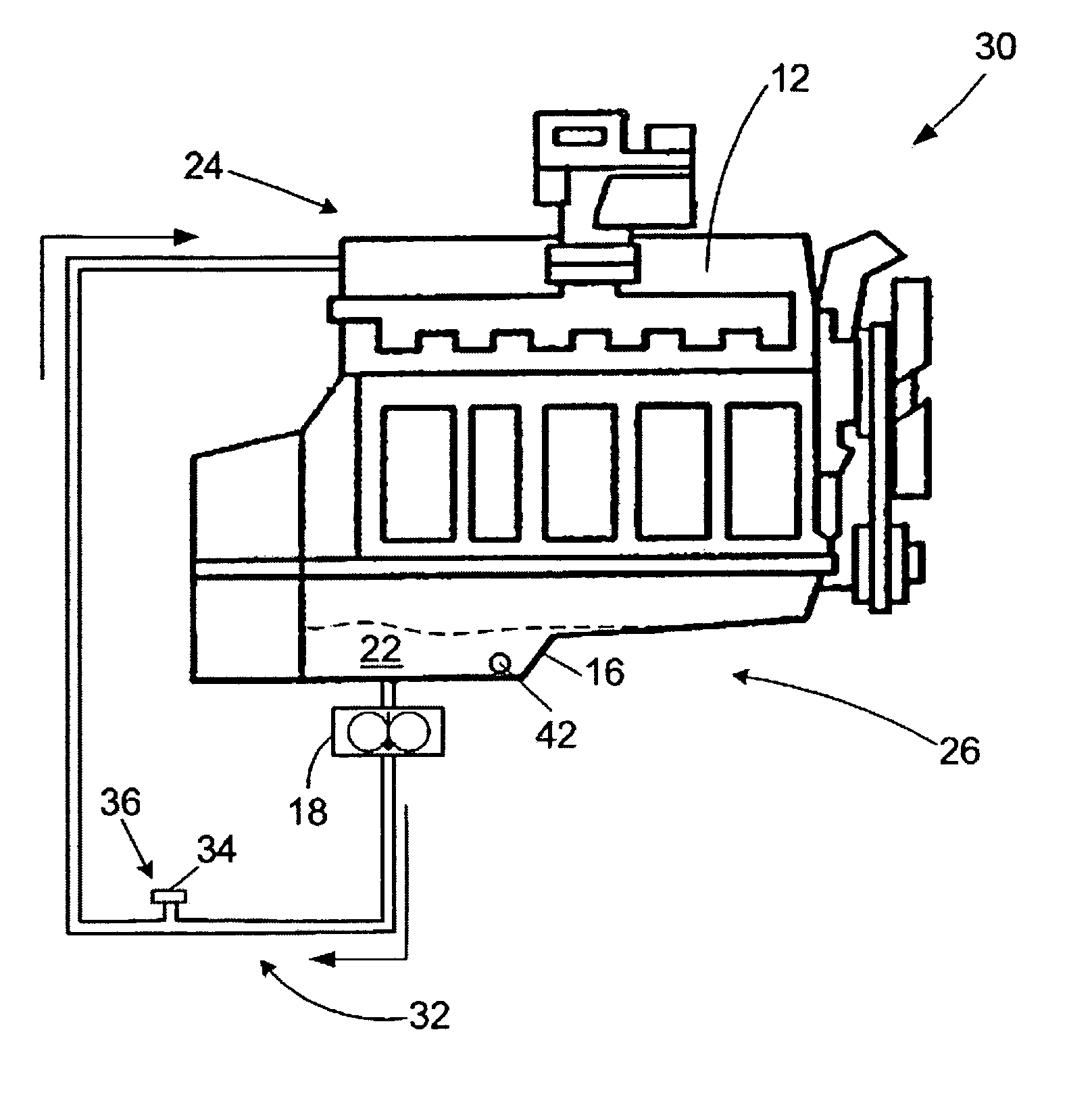
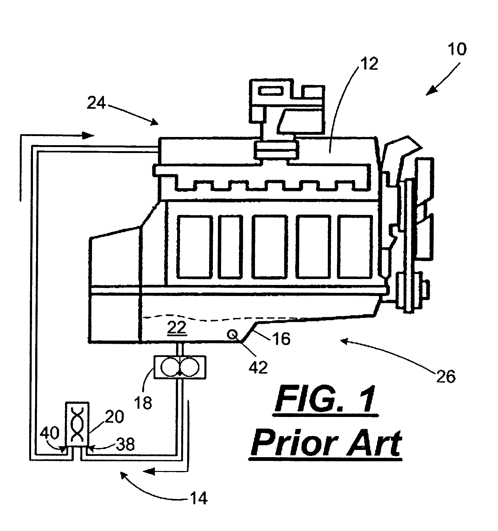
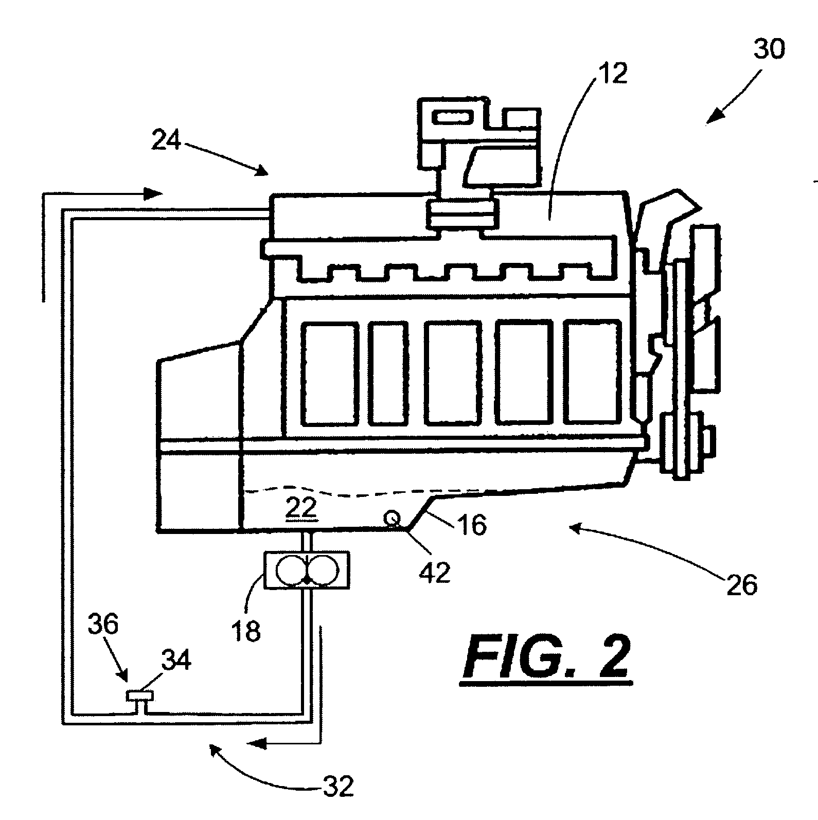
[0012] A conventional engine and crankcase lubrication system 10 are schematically illustrated in FIG. 1. The engine 12 may be any of the commonly used engines in vehicles and other fuel engine containing devices, including, but not limited to compression-ignition engines and spark-ignition engines. The engines 12 typically have separate fuel and lubrication systems. The lubrication system 14 includes an oil pan or oil sump 16, and, optionally, an oil circulation pump 18 or other device known in the art configured to circulate oil or lubricant to moving parts of the engine 12, and a lubricant filter 20. Lubricant 22 in the sump 16 is circulated to an upper portion 24 of the engine 14 so that the lubricant passes through the engine 14 to lubricant moving parts thereof such as the valve train, cylinders, crankshaft and the like. Such lubrication systems 14 may be internal or external to the engine 12.

[0013] In the conventional engine 12, the lubricant 22 is typically changed after a ...


PUM


Abstract

A crankcase lubricating system and method for lubricating an engine of a motor vehicle. The crankcase lubricating system includes filterless lubricant circulation system, and a crankcase lubricant containing a fully formulated lubricating base oil meeting or exceeding ILSAC GF-4 or API CI-4 minimum performance standards for engine oils.

Description

TECHNICAL FIELD [0001] The disclosure is related to vehicles, operation of vehicles and methods for maintaining vehicles, and, in particular, the disclosure is related to filterless crankcase lubrication systems for vehicles. BACKGROUND [0002] Automobiles and other motor vehicles continue to evolve to provide vehicles that require less routine maintenance. For example, vehicle coolant systems no longer require annual flushing and replacement of the coolant. Air intake filters have extended life between replacements. Spark plugs are constructed with exotic materials and do not have to be changed for 50,000 to 100,000 miles. [0003] One advantage of the extended maintenance cycle for various components of a vehicle is that less time is required for a vehicle to be in a shop for routine maintenance. For tractor-trailer rigs hauling goods long distance, routine maintenance is costly from the standpoint that revenue is generated by the number of miles driven. Another advantage of the impr...

Claims


Application Information

Patent Timeline
IPC IPC(8): F01M1/12C10M133/56C10M133/58C10M149/00C10M149/02C10M149/06C10M149/10C10M169/04C10N20/04C10N30/00C10N40/25F01M1/04F01M1/10F16M1/00
CPCC10M133/56C10M133/58C10M149/06C10M149/10C10M2205/022F01M1/10C10M2215/30C10N2220/021C10N2240/102C10N2240/104C10N2260/09C10M2215/28C10M2205/024C10M2209/086C10M2217/06C10M2217/028C10M2217/024C10N2020/04C10N2040/252C10N2040/255C10N2060/09
Inventor VENHAUS, DAVID A.SHAMA, ROBERT A.HORVATH, JAMES M.SZEMENYEI, DEWEY P.ROHFRITCH, RICHARD J.PRIDEMORE, DANNY
Owner AFTON CHEMICAL
Why Eureka
Try Eureka