Linear motion and rotation drive apparatus

a technology of rotation drive and linear motion, which is applied in the direction of propulsion systems, instruments, electric/magnetic position measurements, etc., can solve the problems of increasing the magnitude of inertia when the output shaft is moved linearly or rotated, and achieve the reduction of the size of the sensor substrate, the reduction of the size of the magnetic scale of the linear motion and the rotational position detector in an axial direction, and the effect of easy miniaturization of linear motion

Inactive Publication Date: 2019-02-14
NIDEC CORP
View PDF7 Cites 3 Cited by
  • Summary
  • Abstract
  • Description
  • Claims
  • Application Information

AI Technical Summary

Benefits of technology

[0013]In the present invention, the first magnetic detection element and the second magnetic detection element are preferably stacked above the sensor substrate. Thus, mounting areas of the first magnetic detection element and the second magnetic detection element can be reduced as compared with those of a case in which the first magnetic detection element and the second magnetic detection element are formed above the sensor substrate without being stacked. As a result, since a size of the sensor substrate can be reduced, it can be easy to miniaturize the linear motion and rotation detector.
[0014]In the present invention, the linear motor and the rotational motor can be disposed at different positions in the axial direction. Thus, it can be easy to miniaturize the apparatus in a radial direction as compared with that of a case in which the rotational motor is constituted on the outer circumference side of the linear motor and the linear motor and the rotational motor are coaxially disposed at the same position in the axial direction or a case in which the linear motor is constituted on the outer circumference side of the rotational motor and the linear motor and the rotational motor are coaxially disposed at the same position in the axial direction.
[0015]According to the present invention, a size of a magnetic scale of a linear motion and rotational position detector in an axial direction can be reduced. Since this makes it easier to minimize a weight of the magnetic scale, inertia due to a magnetic scale attached to an output shaft when the output shaft is moved linearly or rotated can be minimized.

Problems solved by technology

Here, if a size of a magnetic scale attached to the output shaft is increased, there is a problem that a magnitude of inertia when the output shaft is moved linearly or rotated is increased because its weight is increased.

Method used


Image

  • Linear motion and rotation drive apparatus
  • Linear motion and rotation drive apparatus
  • Linear motion and rotation drive apparatus

Examples


Embodiment Construction

[0025]Embodiments of the present invention will be described with reference to the drawings.

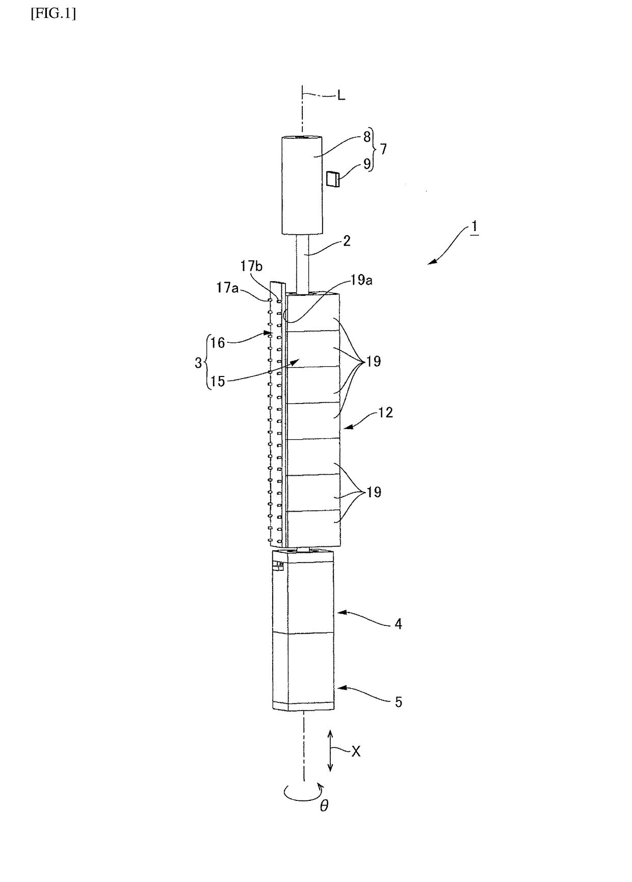
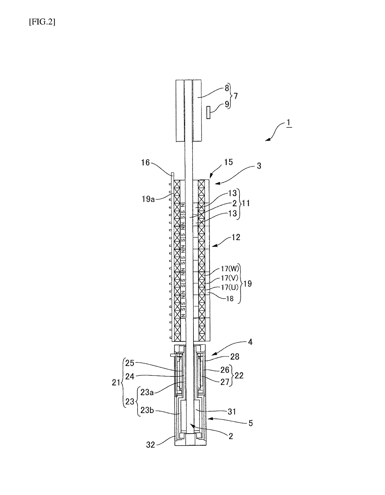
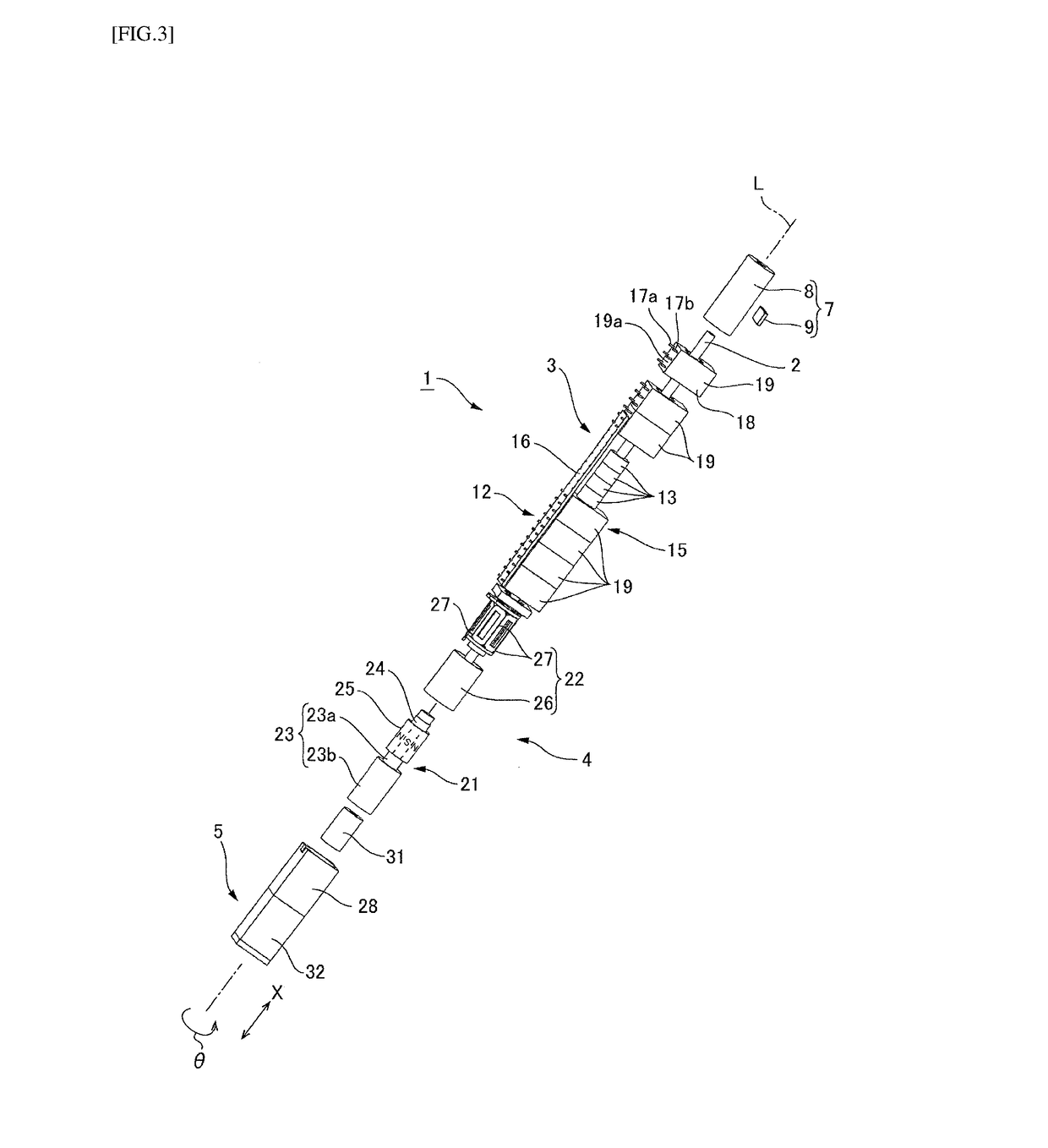
[0026]FIG. 1 is an exterior perspective view of a linear motion and rotation drive apparatus including a linear motion and rotation detector according to the present invention. FIG. 2 is a cross-sectional view of the linear motion and rotation drive apparatus in FIG. 1 taken along a surface thereof cut to include an axis thereof. FIG. 3 is an exploded perspective view of the linear motion and rotation drive apparatus in FIG. 1. As illustrated in FIG. 1, a linear motion and rotation drive apparatus 1 includes an output shaft 2, a linear motor 3 that moves the output shaft 2 along an axis L, a rotational motor 4 that rotates the output shaft 2 in a direction θ around the axis, and a ball spline bearing (bearing) 5. The ball spline bearing 5 supports the output shaft 2 to be movable in an axial direction X and transfers a driving force of the rotational motor 4 to the output shaft 2.

[0027]The li...


PUM


Abstract

Provided is a linear motion and rotation drive apparatus capable of minimizing inertia due to a magnetic scale attached to an output shaft when the output shaft is linearly moved or rotate. A linear motion and rotation drive apparatus (1) includes an output shaft (2), a linear motor (3), a rotational motor (4), a ball spline bearing (5), a magnetic scale (8), a first magnetic detection element (41) configured to detect a linear motion, and a second magnetic detection element (42) configured to detect a rotational motion. The magnetic scale (8) includes a lattice-shaped magnetized pattern (37) in which S poles and N poles are alternately arranged in an axis L direction and S poles and N poles are alternately magnetized in a direction around the axis (L) on a circumferential surface thereof in the direction around an axis (L). The first magnetic detection element (41) and the second magnetic detection element (42) are disposed to face the magnetized pattern (37). Since a linear motion position and a rotating position can be detected using the first magnetic detection element (41) and the second magnetic detection element (42) that face the same magnetized pattern (37), a size of a linear motion and rotation detector (7) in the axis L direction is not increased and a weight thereof is not increased.

Description

BACKGROUND OF THE INVENTION1. Field of the Invention[0001]The present invention relates to a linear motion and rotation drive apparatus including a linear motion and rotation detector that detects a linear motion position and a rotational position of an output shaft.2. Description of the Related Art[0002]Japanese Patent Laid-Open No. 2011-239661 discloses a linear motion and rotation drive apparatus including a motor that linearly moves and rotates an output shaft and a linear motion and rotation detector that detects a linear motion position and a rotational position of the output shaft. In Japanese Patent Laid-Open No. 2011-239661, the linear motion and rotation detector includes a linear motion and rotation scale fixed coaxially with the output shaft, a linear motion detector that faces the linear motion and rotation scale and detects a linear motion position of the output shaft, and a rotation detector that faces the linear motion and rotation scale and detects a rotational posi...

Claims


Application Information

Patent Timeline
Patent Type & Authority Applications(United States)
IPC IPC(8): G01B7/00H02K41/03G01D5/14
CPCG01B7/003H02K41/03G01D5/145G01D5/2451H02K41/031H02K2201/18H02K11/215G01D2205/80G01D2205/90
Inventor KUROSAWA, HIRONORIWATANABE, SOICHIMORIYAMA, KATSUYAARUGA, FUSAYOSHI
Owner NIDEC CORP
Why Eureka
Try Eureka