Input Assistance Device And Drawing System

Active Publication Date: 2019-02-14
BRAIN MAGIC CO LTD
View PDF3 Cites 1 Cited by
  • Summary
  • Abstract
  • Description
  • Claims
  • Application Information

AI Technical Summary

Benefits of technology

The invention is a device that helps users input information while their hand is still spinning. It generates multiple signals without the need for the user to remove their hand from the spinning body.

Problems solved by technology

As desiring to zoom in or out an image or a part of the image (referred as “object” hereafter), to move and rotate the object, and to change drawing tool, the user can only click icon(s) displayed in drawing software or type keyboard without using an indicator device, thus causing inconvenient operation with hand(s).
As desiring to rotate the object, it is essential to rotate the object at each 45 degrees by using the keyboard (such as determining a rotating angle according to a pressing time), but such an operation is not executed easily.
The input assistance device has some functions, such as zooming in or out of the object, a size change of a brush, and a color density change of the brush, but these functions cannot be selected based on types of signals.
However, the user has to remove his / her one hand from the rotary encoder when changing the multiple drawing functions, thus causing troublesome operation.

Method used


Image

  • Input Assistance Device And Drawing System
  • Input Assistance Device And Drawing System
  • Input Assistance Device And Drawing System

Examples


first embodiment

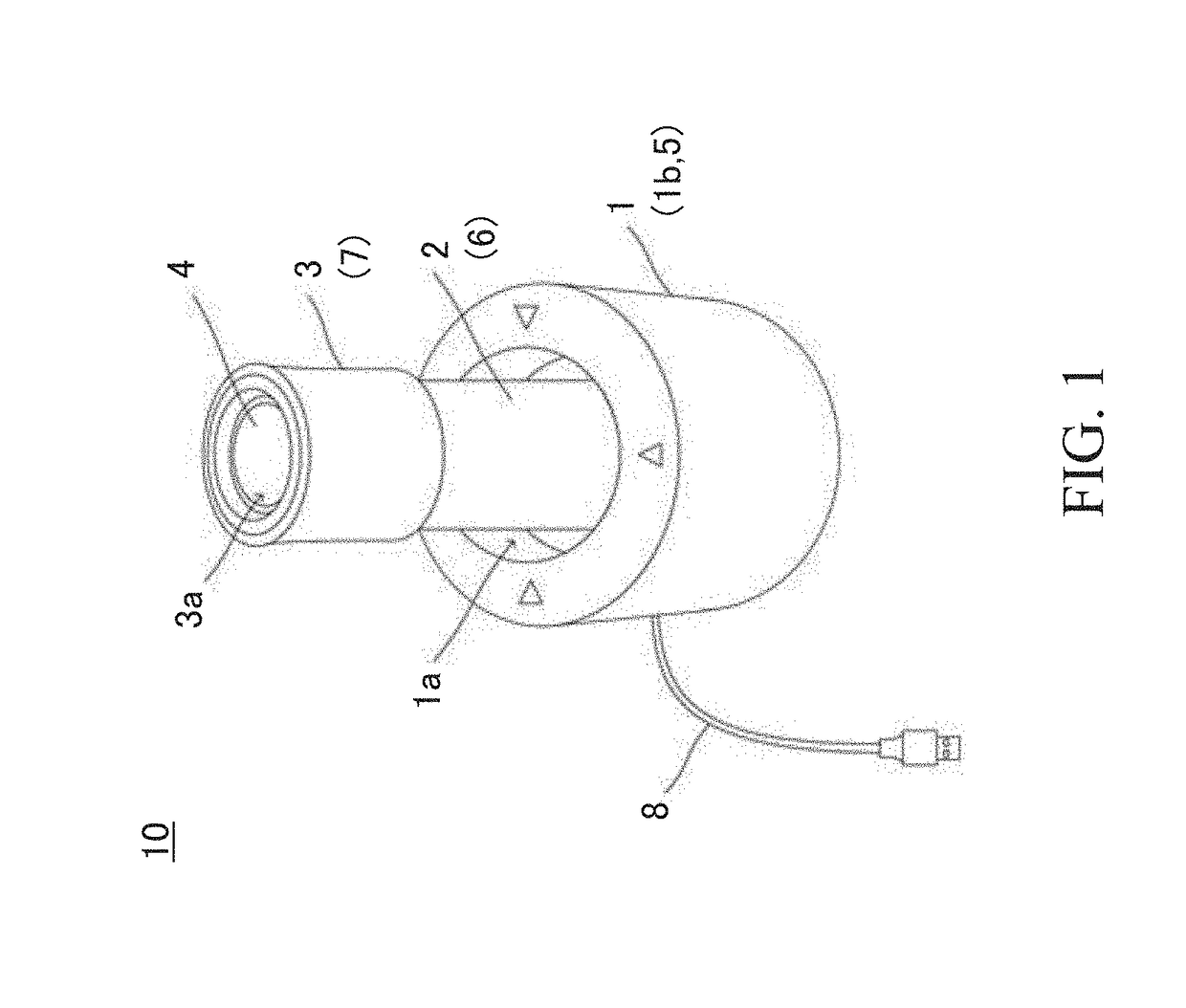
[0058]With reference to FIG. 1, an input assistance device 10 according to the present invention is operated by user independently to generate signals configured to control an objective, and the input assistance device 10 comprises: an operation unit 1, a shaft 2, a first sensor 5, a rotating body 3, a second sensor 6, a switch 4, a detection unit 7, a universal serial bus (USB) cable 8, and a signal generation unit 9. In addition, front, rear, left, and right sides of FIG. 1 are referred to as front, rear, left, and right, respectively.

[0059]The operation unit 1 is configured to accommodate the shaft 2 and is made of resin in a cylinder shape, a width of the operation unit 1 is more than a height of the operation unit 1, and the operation unit 1 includes a cavity la formed on a center of a top thereof and a supporter (not shown) housed in the operation unit 1, wherein the supporter (not shown) has multiple components configured to obliquely support the shaft 2 in the cavity 1a, and...

second embodiment

[0094]FIG. 6 is a flow chart showing the decision process of the signals according to the present invention.

[0095]The signal generation unit 9 includes a first process 91 corresponding to the first and third detection results of the first sensor 5, a second process 92 corresponding to the second detection result of the second sensor 6, and a third process 93 corresponding to the detection result of the detection unit 7.

[0096]The second process 92 and the third process 93 of the second embodiment are identical to those of the first embodiment and are configured to transmit detected signals and the type of the signals.

[0097]The signals of the second detection result of the second sensor 6 include zooming in and zooming out of an object, rotation of the object, a size change of a brush, and a color density change of the brush. The signals of the detection result of the detection unit 7 include undo, redo, a color selection, printing or not respectively. The types of the signals are sel...

third embodiment

[0106]FIG. 8 is a flow chart showing the decision process of the signal according to the present invention. The signal generation unit 9 includes a first process 91 corresponding to the fifth and fifth detection results of the first sensor 5, a second process 92 corresponding to the second detection result of the second sensor 6, and a third process 93 corresponding to the detection result of the detection unit 7.

[0107]The detected signals and the types of the signals (i.e., the rotating angle detected by the second sensor 6 and operation of the switch 4 detected by the detection unit 7) in the second process 92 and the third process 93 are sent so that the user inputs the signals.

[0108]The types of the signals corresponding to the second detection result of the second sensor 6 include zooming in and zooming out of the object, rotation of the object, a size change of a brush, and a color density change of the brush. The types of the signals corresponding to the detection result of t...


PUM


Abstract

Provided is an input assistance device that generates multiple signals without removal of a hand from a rotating body. This input assistance device 10 is equipped with: an operation unit having a shaft 2 that tilts in multiple directions from a neutral position and a rotating body 3 that rotates with respect to the shaft 2; a first sensor 5 that detects the tilt direction of the shaft 2; a second sensor 6 that detects the rotational angle of the rotating body 3; and a signal generation unit 9 that generates signals using the detection result from the first sensor 5 and the detection result from the second sensor 6. Multiple signals can be generated by means of the signal generation unit 9 by selecting the type of signal on the basis of the tilt direction of the shaft 2 as detected by the first sensor 5 and adjusting the size of the signal on the basis of the rotational angle of the rotating body 3 as detected by the second sensor 6.

Description

FIELD OF THE INVENTION[0001]The present invention relates to an input assistance device for generating control signals corresponding to a control objective and a drawing system equipped with the input assistance device.BACKGROUND OF THE INVENTION[0002]When drawing on a computer (making image data), user draws with one hand by way of a pen table and a mouse, etc. As desiring to zoom in or out an image or a part of the image (referred as “object” hereafter), to move and rotate the object, and to change drawing tool, the user can only click icon(s) displayed in drawing software or type keyboard without using an indicator device, thus causing inconvenient operation with hand(s).[0003]It is efficient to draw with one hand by using the indicator device and to edit illustration with the other hand by ways of other devices. Typically, the one hand is user's right hand and the other hand is user's left hand, the device operated by the other hand is called as a left-hand auxiliary input devic...

Claims


Application Information

Patent Timeline
IPC IPC(8): G06F3/0338G06F3/038
CPCG06F3/0338G06F3/0383G06T11/60G06F3/038G05G9/04792G05G9/04796G05G9/047
Inventor KANNARI, DAIKI
Owner BRAIN MAGIC CO LTD
Why Eureka
Try Eureka