Color gradient paths

Inactive Publication Date: 2005-10-27
MICROSOFT TECH LICENSING LLC
View PDF18 Cites 34 Cited by
  • Summary
  • Abstract
  • Description
  • Claims
  • Application Information

AI Technical Summary

Benefits of technology

[0009] The present invention provides a system and method to facilitate generation of smooth color gradients using techniques from geometric surface modeling. The system and method of the present invention allow designers to specify very complex gradients in a simple way. A visual designer can edit the color gradient after it is created, and these color gradients can be generated (e.g., very quickly) in accordance with an aspect of the present invention. The resulting color gradient has smoothly varying colors and scales well across various output devices (e.g., form factors and/or display configurations). Color gradients generated in accordance with the present invention enable users to quickly and easily create rich and smooth color gradients that can be efficiently drawn using computer graphics hardware.
[0010] One aspect of the present invention provides for graphic representations of color gradients to have a compact representation when compared with conventional graphic representations of gradients. Thus, unlike bitmaps, which often contain a large quantity information, graphic representations based on color gradients generated in accordance with the present invention can be compact; a color gradient generated in accordance with the present invention can be specified usin

Problems solved by technology

The linear gradient is the most basic gradient of all and is typically not complex enough for advanced effects.
The mesh gradient is more advanced than both linear and radial gradients; however, complex mesh gradients put a heavy burden on the users, as they can only be achieved by specifying the positions and colors of many control points.
A gradient mesh is more powerful, b

Method used


Image

  • Color gradient paths
  • Color gradient paths
  • Color gradient paths

Examples


Example

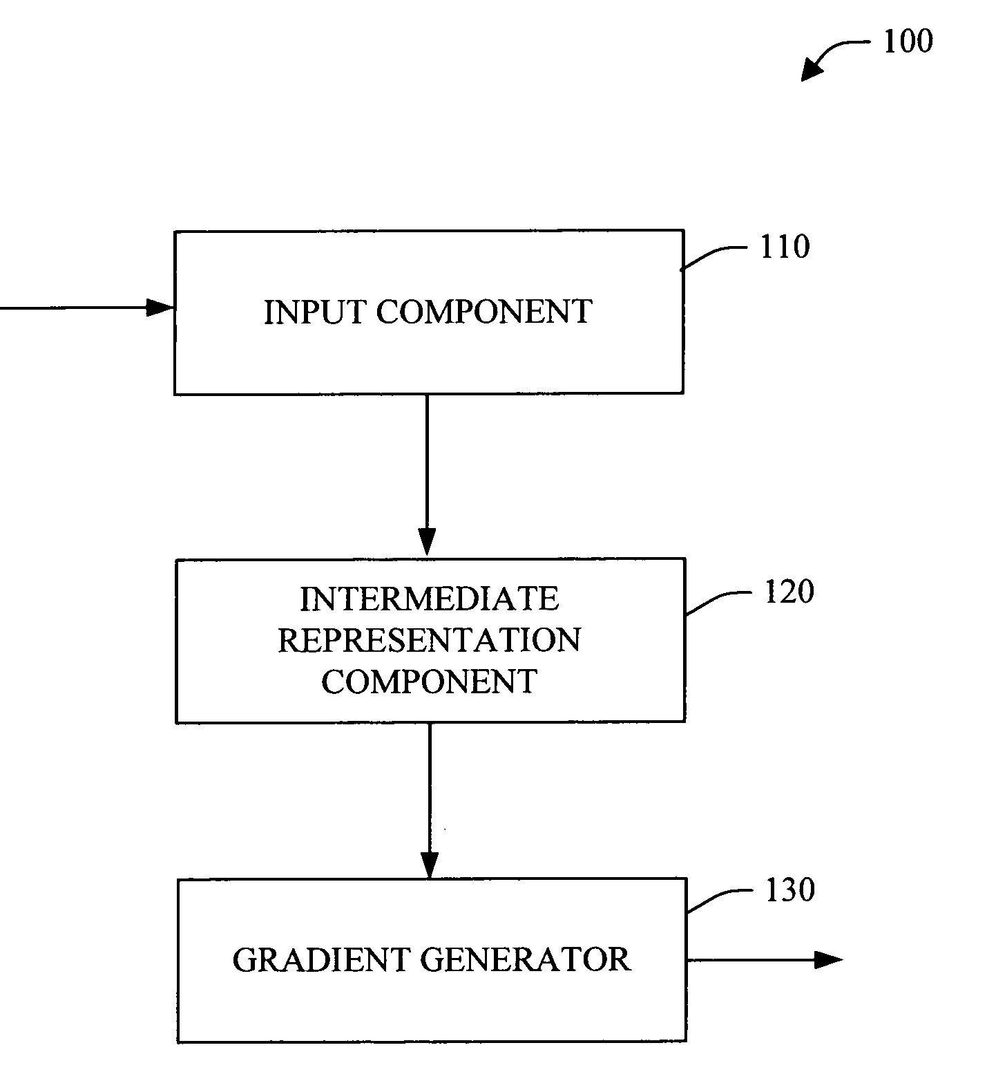
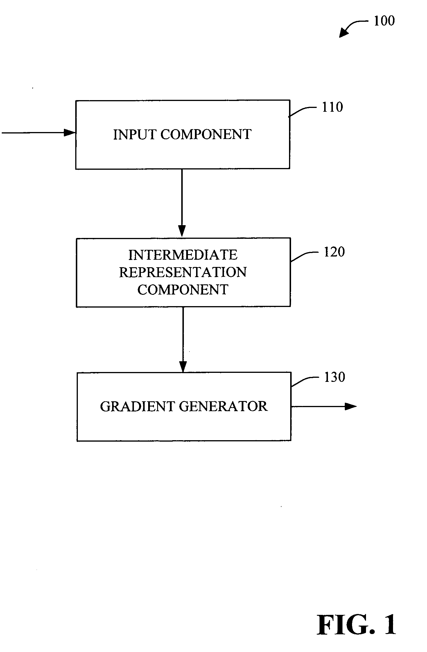
[0034] The present invention is now described with reference to the drawings, wherein like reference numerals are used to refer to like elements throughout. In the following description, for purposes of explanation, numerous specific details are set forth in order to provide a thorough understanding of the present invention. It may be evident, however, that the present invention may be practiced without these specific details. In other instances, well-known structures and devices are shown in block diagram form in order to facilitate describing the present invention.

[0035] As used in this application, the term “computer component” is intended to refer to a computer-related entity, either hardware, a combination of hardware and software, software, or software in execution. For example, a computer component may be, but is not limited to being, a process running on a processor, a processor, an object, an executable, a thread of execution, a program, and / or a computer. By way of illust...


PUM


Abstract

A system and method for generating color gradients is provided. The system generates color gradients using techniques from geometric surface modeling. The system and method of the present invention allow designers to specify very complex gradients in a simple way. The system can employ, for example, a vector-based interpolation method and/or a pixel-based partial differential equation (PDE) interpolation methods to facilitate generation of the color gradients. In one example, input boundary curves and/or feature curves are approximated by line segments, which are then utilized to generate a triangulation approximating a smooth color gradient.

Description

CROSS-REFERENCE TO RELATED APPLICATIONS [0001] This application is a continuation of U.S. patent application Ser. No. 10 / 601,428, filed Jun. 23, 2003, entitled “COLOR GRADIENT PATHS,” which is a Continuation-in-Part application of U.S. patent application Ser. No. 10 / 417,937, now U.S. Pat. No. 6,856,705, filed on Apr. 16, 2003, entitled “IMAGE BLENDING BY GUIDED INTERPOLATION,” which is an application claiming benefit under 35 U.S.C §119(e) to U.S. Provisional Patent Application Ser. No. 60 / 450,078, filed on Feb. 25, 2003, entitled “IMAGE BLENDING BY GUIDED INTERPOLATION.” The entireties of the above-noted applications are incorporated herein by reference.TECHNICAL FIELD [0002] The present invention relates generally to computer graphics, and, more particularly to a system and method to facilitate smooth color gradient(s) by employing color gradient path(s). BACKGROUND OF THE INVENTION [0003] Many computer paint and drawing programs allow a user to fill an area with a single and / or m...

Claims


Application Information

Patent Timeline
IPC IPC(8): G06T1/00G06T5/00G06T11/00G06T11/40H04N1/46H04N1/60
CPCG06T11/001G06T11/40
Inventor GANGNET, MICHEL J.KALLAY, MICHAELWU, ANDREW Y.STOLLNITZ, ERIC J.STRAWN, DEVON L.LOUNSBERY, JOHN MICHAELPEREZ, PATRICK
Owner MICROSOFT TECH LICENSING LLC
Why Eureka
Try Eureka