Signal transmitting device suited to fast signal transmission
- Summary
- Abstract
- Description
- Claims
- Application Information
AI Technical Summary
Benefits of technology
Problems solved by technology
Method used
Image
Examples
first embodiment
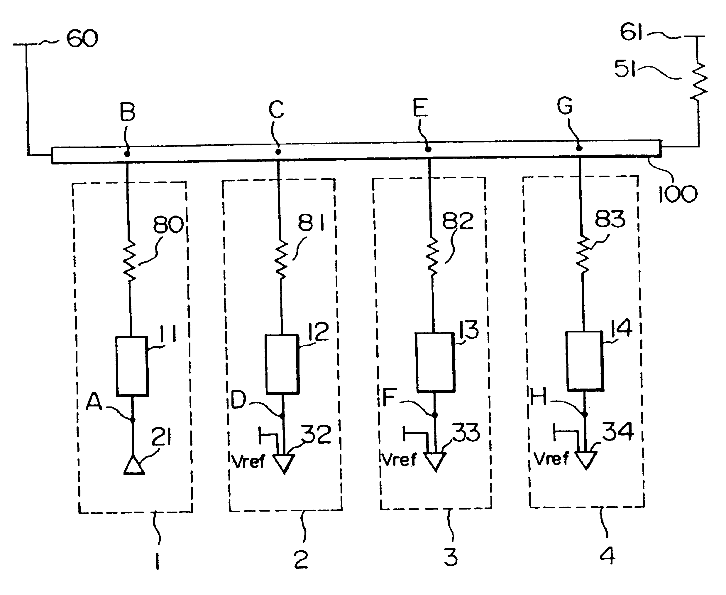
FIG. 4 shows in fundamental block diagram, a unidirectional transmission line to which the present invention is applied.
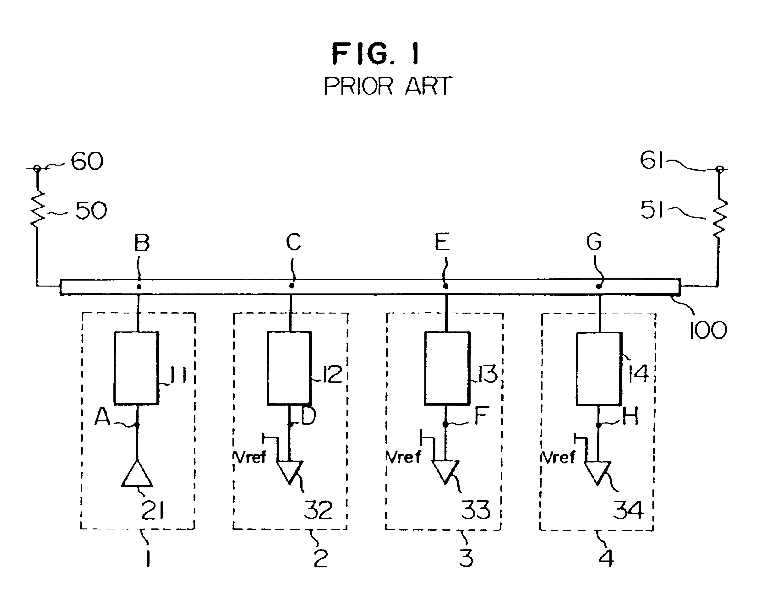
In FIG. 4, a numeral 1 denotes a driving circuit block (unit) having a driving circuit 21. Numerals 2 to 4 denote receiving circuit blocks provided with receiving circuits 32 to 34, respectively. The circuit blocks include resistors 80 to 83 and transmission lines 11 to 14, respectively. A transmission line 100 is connected to the circuit blocks 1 to 4, and both ends of the transmission bus 100 are terminated by the resistors 50 and 51, each having a resistance equal to or close to a characteristic impedance value of the transmission line 100.
In FIG. 4, the transmission line 100 has an impedance of 50 Ω. The branched lines 11 to 14 each have an impedance of 100 Ω. Each of the termination resistors 50 and 51 has a resistance of 50 Ω. Terminating power supplies 60 and 61 operate to supply a voltage of 1.5 V. The driving circuit 21 has an on resistance of 10 Ω.
The dri...
embodiment 2
The following description will be directed to embodiment 2 in which the present invention is applied to a bidirectional transmission line.
FIG. 11 is a fundamental block diagram showing the second embodiment. The circuit blocks 1 to 4 provide driving circuits 21 to 24, receiving circuits 31 to 34, resistors 80 to 83, and transmission lines 11 to 14, respectively. A transmission line 100 is connected to the circuit blocks 1 to 4 and is terminated by the resistors 50 and 51, each having a resistance equal to a characteristic impedance value of the transmission line 100.
FIG. 11 shows the transmission line terminated at both ends by the resistors. However, if desired, the transmission bus may be terminated at one end by one resistor. Further, FIG. 11 shows four blocks. In actuality, the present invention may apply to any transmission line if it is connected to two or more blocks.
The arrangements of the driving circuits 21 to 24 and the receiving circuits 31 to 34 included in the circuit ...
embodiment 3
The following description will be directed to a third embodiment which is particularly effective in the case of providing a large capacitance at the tip of each branched line in a situation where there are many branched lines. FIG. 14 is a fundamental block diagram for explaining a unidirectional transmission bus according to this embodiment. FIG. 15 is a fundamental block diagram for explaining a bidirectional transmission bus according to this embodiment. In FIG. 14, a circuit block 1 includes a driving circuit 21, and circuit blocks 2 to 4 include receiving circuits 32 to 34, respectively. Further, the blocks have resistors 80 to 83 and transmission lines 11 to 14, respectively. In FIG. 15, the circuit blocks 1 to 4 provide sending circuits 21 to 24, receiving circuits 31 to 34, resistors 80 to 83, and transmission lines 11 to 14, respectively. In FIGS. 14 and 15, the transmission line 100 is connected to the circuit blocks 1 to 4, and is terminated by resistors 50 and 51 each ha...
PUM
 Abstract
Description
Claims
Application Information
 - R&D
- Intellectual Property
- Life Sciences
- Materials
- Tech Scout
- Unparalleled Data Quality
- Higher Quality Content
- 60% Fewer Hallucinations
Browse by: Latest US Patents, China's latest patents, Technical Efficacy Thesaurus, Application Domain, Technology Topic, Popular Technical Reports.
© 2025 PatSnap. All rights reserved.Legal|Privacy policy|Modern Slavery Act Transparency Statement|Sitemap|About US| Contact US: help@patsnap.com


