Transceiver phtonic integrated circuit

Active Publication Date: 2011-10-06
INFINERA CORP
View PDF7 Cites 50 Cited by
  • Summary
  • Abstract
  • Description
  • Claims
  • Application Information

AI Technical Summary

Benefits of technology

[0013]Consistent with still further aspects of the present disclosure, the transceiver comprises one or more amplitude varying elements which may act to amplify, attenuate, or amplify and attenuate the amplitude of one or more of the optical signals propagating through the transceiver. Such optical signals may, for example, be multiplexed optical signals. In some embodiments, such amplitude varying elements may include semiconductor optical amplifiers, variable opt

Problems solved by technology

However, systems designed to transmit and receive Pol Mux DQPSK signals, however, typically have additional components, both active and passive, and greater complexity than transmitters and receivers designed for use with other modulating techniques.

Method used


Image

  • Transceiver phtonic integrated circuit
  • Transceiver phtonic integrated circuit
  • Transceiver phtonic integrated circuit

Examples


Embodiment Construction

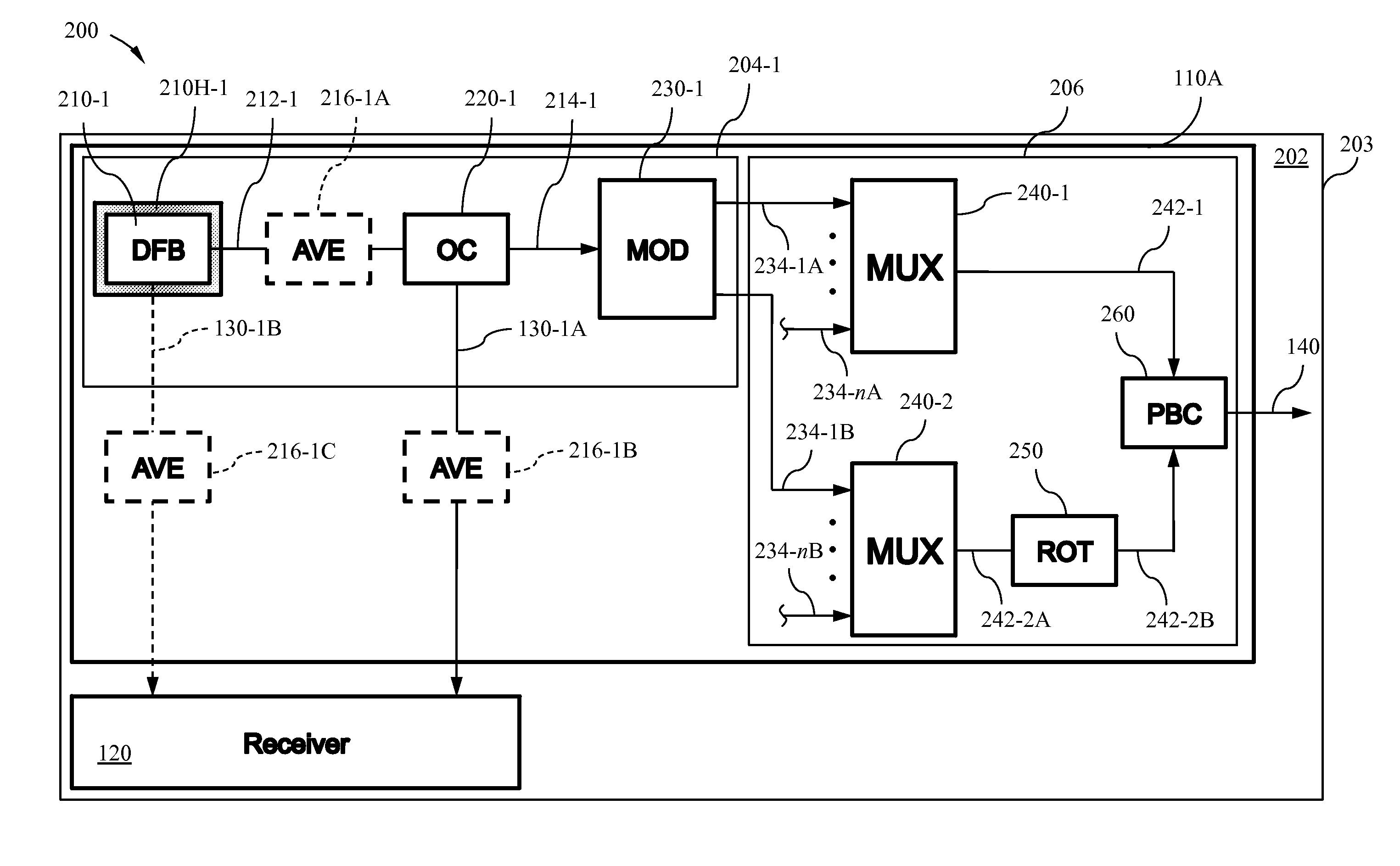
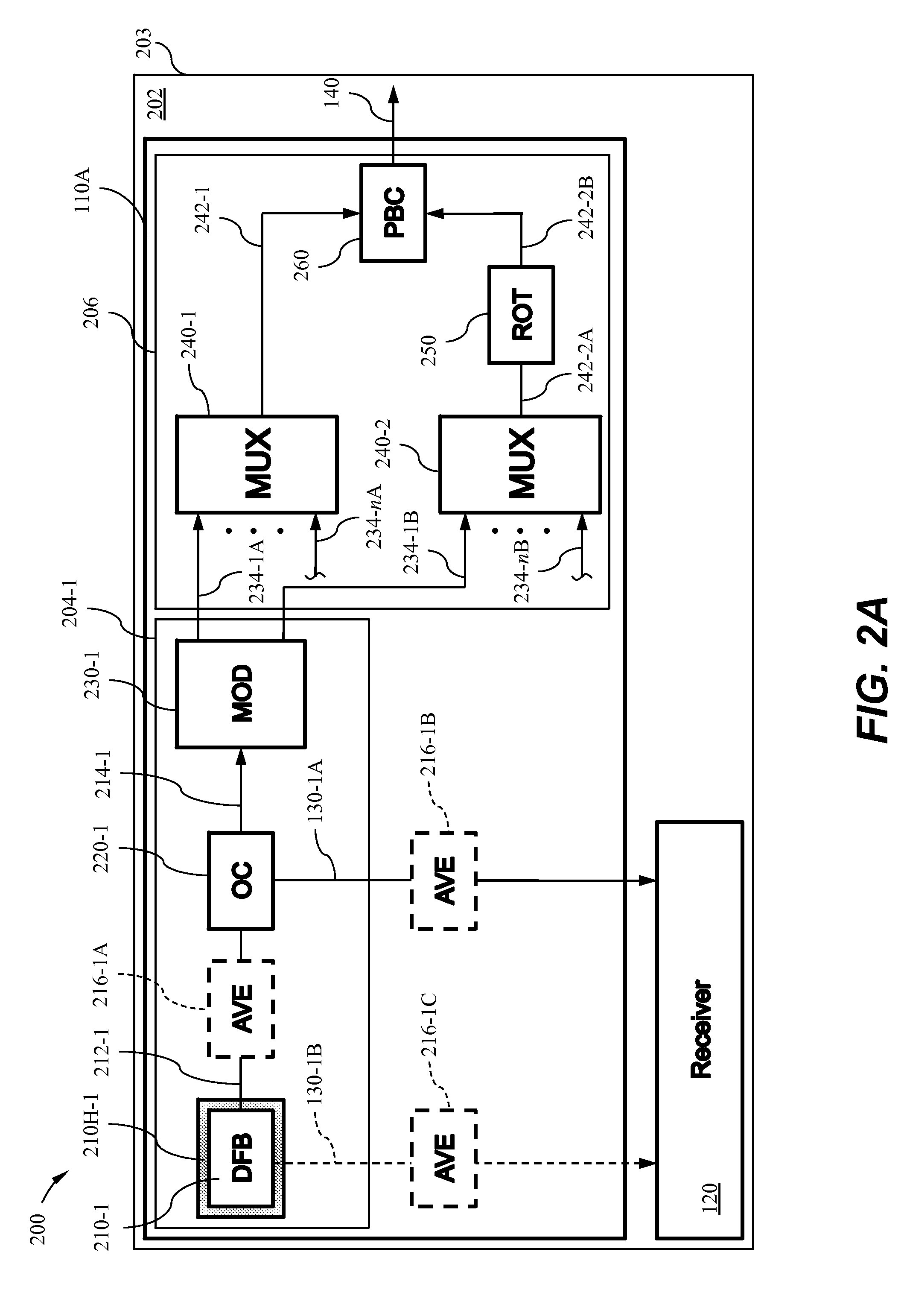
[0030]A coherent optical transceiver circuit is disclosed in which various components of the optical transceiver may be provided or integrated, in one example, on a common substrate. The optical transceiver circuit may be used to demultiplex various phase shift keying optical signals, such as quadrature phase-shift keying (QPSK), polarization quadrature phase-shift keying, or polarization multiplexed phase-shift keying signals.

[0031]The following description is set forth for purpose of explanation in order to provide an understanding of the invention. However, it is apparent that one skilled in the art will recognize that embodiments of the present invention, some of which are described below, may be incorporated into a number of different systems and devices.

[0032]The embodiments of the present invention may include certain aspects each of which may be present in hardware, software or firmware. Structures and devices shown below in block diagram are illustrative of exemplary embodi...


PUM


Abstract

The present invention provides for a transceiver comprising a transmitter portion and a receiver portion. The transmitter portion includes a laser, the laser providing an optical signal having one of a plurality of wavelengths. The optical signal from the laser is modulated to create a first wavelength-division multiplexed signal at an output of the transceiver. The optical signal from the laser is also used by a demultiplexer to demultiplexer a second wavelength-division multiplexed signal at an input of the transceiver. The use of the optical signal from the laser in both modulation and demodulation of wavelength-division multiplexed signals results in a transceiver having fewer discrete components resulting in a compact design and reduced costs.

Description

BACKGROUND OF THE INVENTION[0001]1. Field of the Invention[0002]This invention relates generally to optical telecommunication systems and, more particularly, to transceivers comprising photonic integrated circuits employed in such systems.[0003]2. Description of the Related Art[0004]Wavelength-division multiplexed (WDM) optical communication systems are known in which multiple optical signals, each having a different wavelength, are combined onto a single optical fiber. Such systems typically include transmitters at an ingress of a network infrastructure of the optical communication system and receivers at an egress of the network infrastructure. Exemplary transmitters may include a plurality of signal channels, each including a laser associated with a particular wavelength, a modulator configured to modulate the output of the laser to provide a modulated signal, and an optical combiner to combine each of the modulated signals into a multiplexed output for delivery over the network ...

Claims


Application Information

Patent Timeline
IPC IPC(8): H04J14/00
CPCH04B10/142H04J14/06H04J14/02H04B10/40
Inventor NAGARAJAN, RADHAKRISHNAN L.KATO, MASAKIKISH, JR., FRED A.WELCH, DAVID F.JOYNER, CHARLES H.
Owner INFINERA CORP
Why Eureka
Try Eureka