Illumination device and projector

Active Publication Date: 2019-02-21
SEIKO EPSON CORP
View PDF1 Cites 1 Cited by
  • Summary
  • Abstract
  • Description
  • Claims
  • Application Information

AI Technical Summary

Benefits of technology

[0021]The projector according to the aspect of the invention is provided wi

Problems solved by technology

When irradiating the display panel with the colored light beams different in cross-sectional size from each other in a converged manner to project an image as described above, there is a problem that color unevenness occurs.
However, if the

Method used


Image

  • Illumination device and projector
  • Illumination device and projector
  • Illumination device and projector

Examples


Example

[0039]Hereinafter, a first embodiment of the invention will be described using FIG. 1 through FIG. 12.

[0040]A projector according to the present embodiment is an example of a liquid crystal projector equipped with a light source device using a semiconductor laser.

[0041]It should be noted that in each of the following drawings, the constituents are shown with the scale ratios of respective sizes set differently between the constituents in some cases in order to facilitate the visualization of each of the constituents.

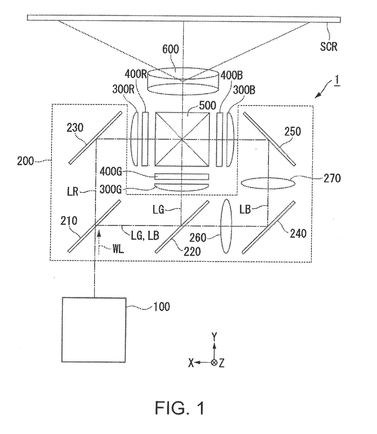
[0042]FIG. 1 is a schematic configuration diagram of the projector 1 according to the present embodiment.

[0043]As shown in FIG. 1, the projector 1 is provided with an illumination device 100, a color separation light guide optical system 200, a red-light light modulation device 400R, a green-light light modulation device 400G, a blue-light light modulation device 400B, a cross dichroic prism 500, and a projection optical system 600. The red-light light modulation device ...

Example

Second Embodiment

[0117]Hereinafter, a second embodiment of the invention will be described using FIG. 13 and FIG. 14.

[0118]The basic configuration of a projector and an illumination device according to the second embodiment is roughly the same as that in the first embodiment, and the configuration of the light beam magnifying optical system is different from that of the first embodiment. Therefore, the description of the whole of the projector and the illumination device will be omitted, and only the light beam magnifying optical system will be described.

[0119]FIG. 13 is a diagram of the light beam magnifying optical system of the second embodiment viewed from the Z direction. FIG. 14 is a diagram of the light beam magnifying optical system of the second embodiment viewed from the X direction.

[0120]In FIG. 13 and FIG. 14, the constituents common to the drawings used in the first embodiment are denoted by the same reference symbols, and the description thereof will be omitted.

[0121]A...

Example

Third Embodiment

[0126]Hereinafter, a third embodiment of the invention will be described using FIG. 15 and FIG. 16.

[0127]The basic configuration of a projector and an illumination device according to the third embodiment is roughly the same as that in the first embodiment, and the configuration of the light beam magnifying optical system is different from that of the first embodiment. Therefore, the description of the whole of the projector and the illumination device will be omitted, and only the light beam magnifying optical system will be described.

[0128]FIG. 15 is a diagram of the light beam magnifying optical system of the third embodiment viewed from the Z direction. FIG. 16 is a diagram of the light beam magnifying optical system of the third embodiment viewed from the X direction.

[0129]In FIG. 15 and FIG. 16, the constituents common to the drawings used in the first embodiment are denoted by the same reference symbols, and the description thereof will be omitted.

[0130]As sho...


PUM


Abstract

An illumination device includes a first light source section which includes at least one first light emitting element adapted to emit first colored light collimated, and is adapted to emit first light including the first colored light, and a light beam magnifying optical system adapted to magnify the first light. The light beam magnifying optical system includes first through fourth lens surfaces arranged in sequence from an incident side of the first light, the first lens surface is formed of a spherical surface having power, the second lens surface is formed of a first anamorphic surface having power with the same sign as the sign of the power of the first lens surface, the third lens surface is formed of a second anamorphic surface having positive power, and the fourth lens surface is formed of a spherical surface having positive power.

Description

BACKGROUND1. Technical Field[0001]The present invention relates to an illumination device and a projector.2. Related Art[0002]There has been proposed an illumination device using a laser element and a phosphor as an illumination device used in, for example, a projector. In JP-A-2013-65414 (Document 1), there is disclosed a projection device provided with an illumination system having a blue laser source, a red laser source, and a green phosphor, liquid crystal panels for respectively modulating the blue light, the red light, and the blue light from the illumination system, and a projection optical system.[0003]In this projection device, the blue light from the blue laser source is branched by a half mirror, and one of the branched blue light beams enters the liquid crystal panel for the blue light, and the other enters a green phosphor as excitation light. The green fluorescence generated by the green phosphor enters the liquid crystal panel for the green light. The red light from t...

Claims


Application Information

Patent Timeline
IPC IPC(8): G03B21/20
CPCG03B21/208G03B21/2033G03B21/2013G03B33/12
Inventor AKIYAMA, KOICHI
Owner SEIKO EPSON CORP
Why Eureka
Try Eureka