Focusing device for beam projector

Active Publication Date: 2011-03-24
SAMSUNG ELECTRONICS CO LTD
View PDF2 Cites 4 Cited by
  • Summary
  • Abstract
  • Description
  • Claims
  • Application Information

AI Technical Summary

Benefits of technology

[0015]The focusing device for a beam, as described above, has an advantage in that it can be easily miniaturized since a control knob and a lens holder are installed adjacent to each other. In addition, since a coupling protrusion is formed on the control knob and a coupling piece is located on a movable member fixed to the lens holder, wherein a bore capable of fully receiving the movable extent of the coupling protrusion is formed through the coupling piece, it is possible to prevent the coupling protrusion and the lens holder from being damaged. That is, since the movable extent

Problems solved by technology

However, if the user applies excessive force when the lens holder has arrived at the end of the available space, the teeth of the rack and pinion gear may be damaged.
Moreover, a rack and pinion gear is provided in a compact portable terminal are often damaged when the portable terminal is dropped.
However, there is a disadvantage in that since the moving space of the connecting rod is maintained in an opened state, internal structures, such as the lens ho

Method used


Image

  • Focusing device for beam projector
  • Focusing device for beam projector
  • Focusing device for beam projector

Examples


Example

[0023]Hereinafter, certain embodiments of the present invention will be described with reference to the accompanying drawings. In the following description, a detailed description of known functions and configurations incorporated herein will be omitted where it may confuse the subject matter of the present invention.

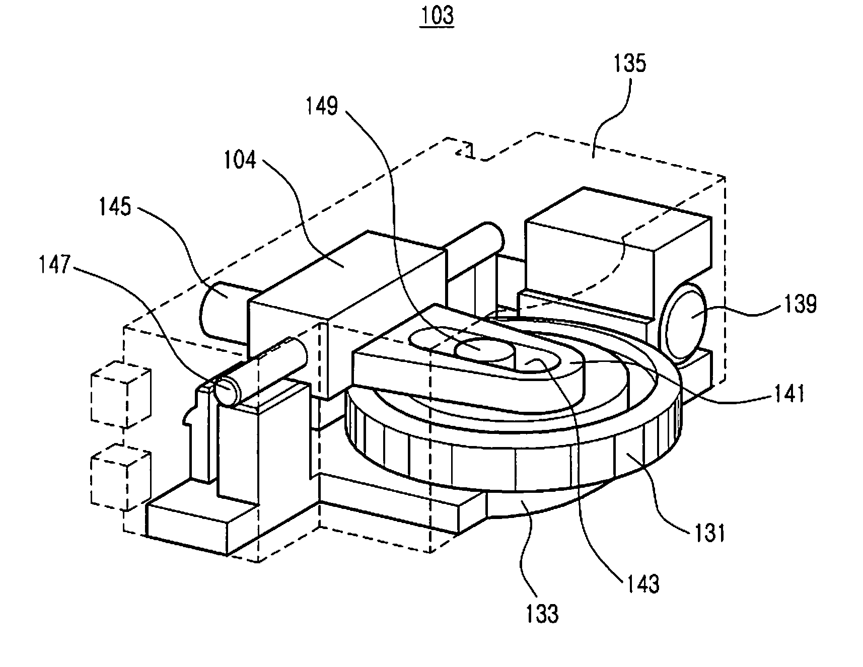
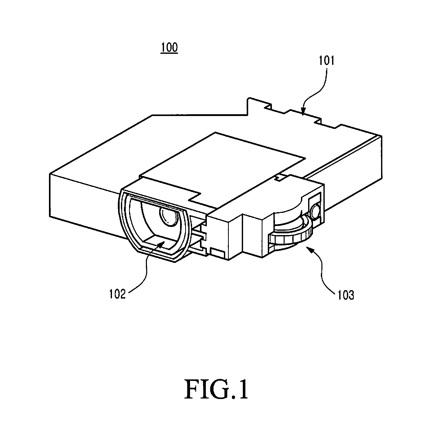
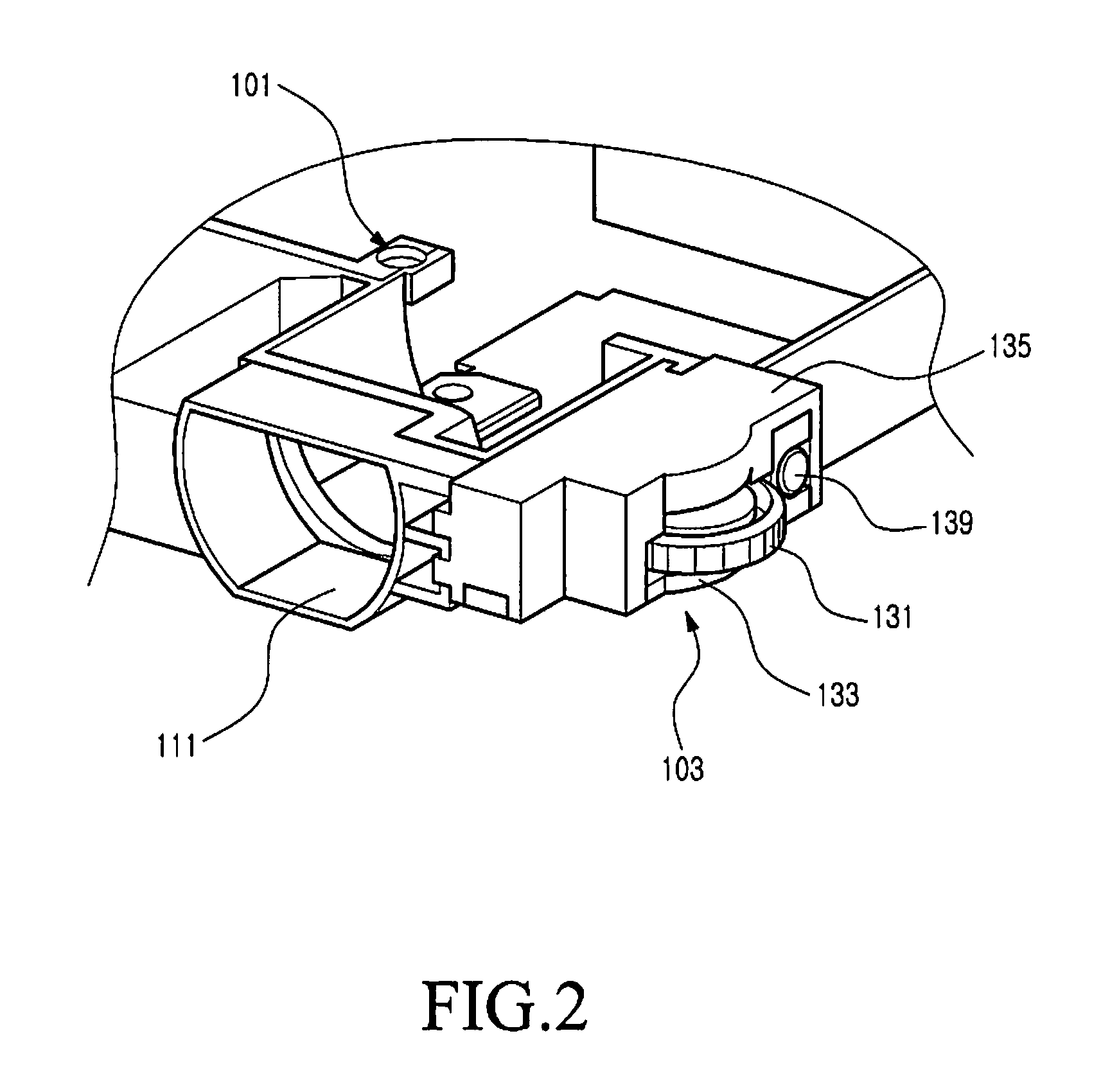
[0024]FIG. 1 is a perspective view illustrating a focusing device of a beam projector in accordance with an embodiment of the present invention, and FIG. 2 illustrates an enlarged perspective view of the focusing module shown inFIG. 1.

[0025]As shown in FIGS. 1 and 2, a focusing device in accordance with an embodiment of the present invention includes a focusing module 103 for moving a lens holder 102 forward or backward, which is mounted on a side of a casing 101. Here, the focusing module 103 is located adjacent to the lens holder 102. In particular, the focusing module 103 is mounted on the outer surface of the casing 101, and the lens holder 102 is mounted in a state...


PUM


Abstract

A focusing device for a beam projector which includes a casing; a lens holder having at least one lens which is movable forward or backward in the direction of the optical axis; a movable member located at a side of the lens holder to be movable parallel to the direction of the optical axis together with the lens holder; and a control knob located adjacent to the lens holder and rotatably coupled on the casing.

Description

PRIORITY[0001]This application claims priority under 35 U.S.C. §119(a) to an application entitled “Focusing Device For Beam Projector” filed in the Korean Industrial Property Office on Sep. 22, 2009, and assigned Serial No. 10-2009-0089669, the contents of which are hereby incorporated by reference.BACKGROUND OF THE INVENTION[0002]1. Field of the Invention[0003]The present invention relates generally to a beam projector, and more particularly to a focusing device for an ultra-compact beam projector that is mountable on a compact appliance, such as a portable terminal.[0004]2. Description of the Related Art[0005]A beam projector is a device which includes a light source, one or more Liquid Crystal Display (LCD) panels, one or more lenses, or the like, wherein light projected from the light source is transmitted through the LCD panels to project an image displayed on the LCD panels onto a screen. The number of the LCD panels and the number of the lenses may vary according to the type ...

Claims


Application Information

Patent Timeline
IPC IPC(8): G02B7/04
CPCG03B21/14G02B7/08G03B3/02G03B21/142G03B21/53
Inventor PARK, JOONG-WANPARK, MUN-KUE
Owner SAMSUNG ELECTRONICS CO LTD
Why Eureka
Try Eureka