Motor unit

Active Publication Date: 2020-09-17
HITACHI ASTEMO LTD +1
View PDF0 Cites 0 Cited by
  • Summary
  • Abstract
  • Description
  • Claims
  • Application Information

AI Technical Summary

Benefits of technology

[0020]According to the aspect (5), the first case includes a first refrigerant passage that cools the first stator from an inner circumferential surface of the first case, the second case includes a second refrigerant passage that cools the second stator from an inner circumferential surface of the second case, and the first and second refrigerant passages are disposed away from the recess. Thereby, the following effect is produced. Since the swell can be incorporated with a portion other than the first refrigerant passage in the first case and a portion other than the second refrigerant passage in the second case, the motor unit can be miniaturized while cooling the first and second stators.
[0021]According to the aspect (6), the swell is provided between the first

Problems solved by technology

However, since the drive unit is disposed parallel to the terminal of the coil end in an ax

Method used


Image

  • Motor unit
  • Motor unit
  • Motor unit

Examples


first embodiment

[0028]100>

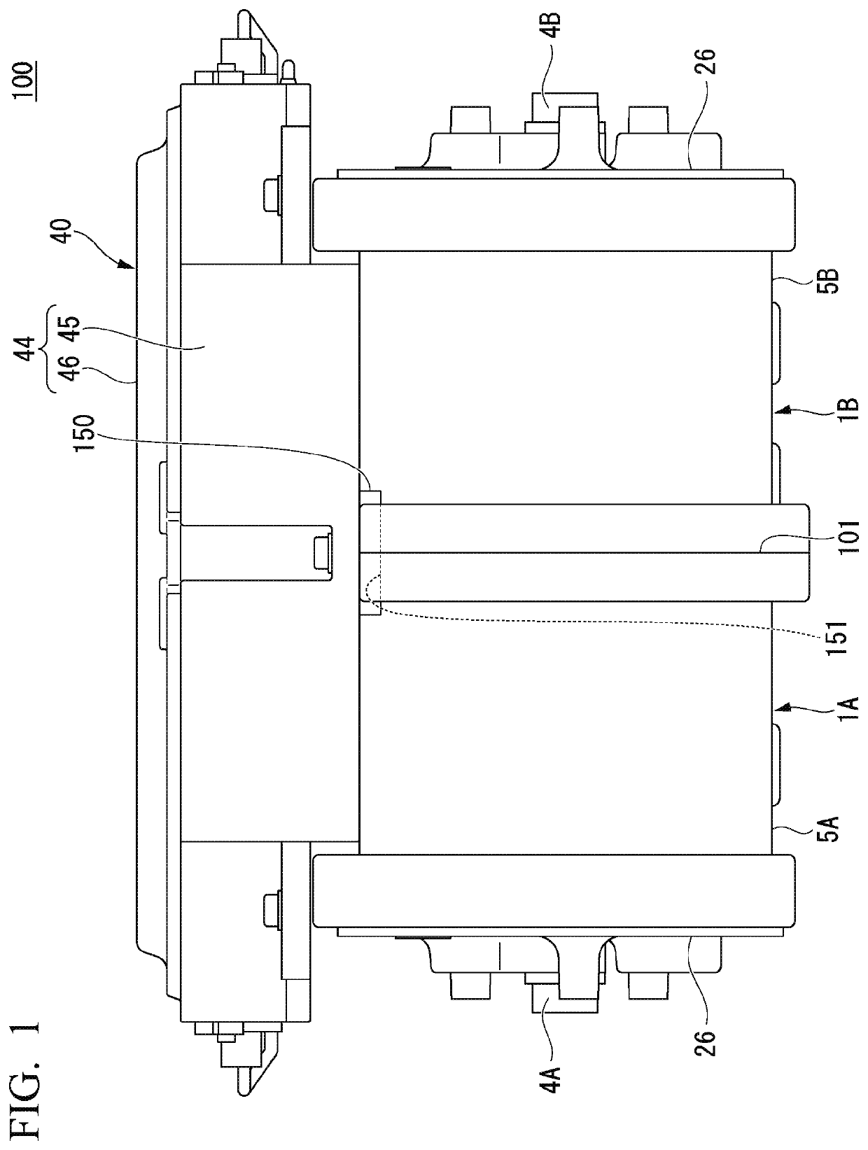
[0029]FIG. 1 is a schematic view of a motor unit 100 according to a first embodiment.

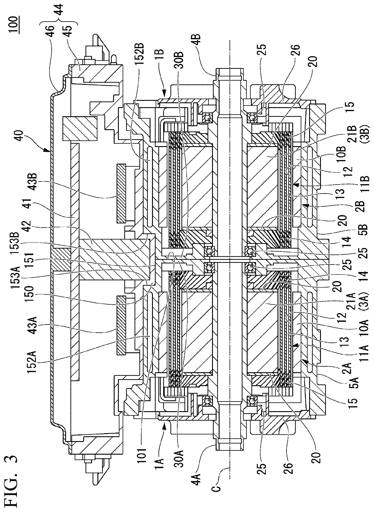
[0030]As illustrated in FIG. 1, the motor unit 100 is a twin motor unit having two rotary electrical machines 1A and 1B. As illustrated in FIG. 3, the two rotary electrical machines 1A and 1B are a first rotary electrical machine 1A and a second rotary electrical machine 1B disposed coaxially with the first rotary electrical machine 1A. The first rotary electrical machine 1A and the second rotary electrical machine 1B are rotatably disposed independently of each other. Hereinafter, a direction along an axis C of the rotary electrical machine is referred to as “axial direction,” a direction perpendicular to the axis C is referred to as “radial direction,” and a direction around the axis C is referred to as “circumferential direction.”

[0031]In the present embodiment, the motor unit 100 is disposed along the axis C in a horizontal direction. In the following description, “A” may be added to t...

second embodiment

[0080]Hereinafter, a second embodiment of the present invention will be described. In the second embodiment, the same components as in the first embodiment are given the same reference signs, and detailed description thereof will be omitted.

[0081]In the aforementioned first embodiment, the constitution in which the motor unit is the twin motor unit having the two rotary electrical machines has been described, but it is not limited thereto. For example, the motor unit may be a single motor unit having a single rotary electrical machine.

[0082]FIG. 4 is a sectional view illustrating a motor unit 200 according to a second embodiment and corresponding to FIG. 3.

[0083]As illustrated in FIG. 4, the motor unit 200 includes a single rotary electrical machine 201 and a drive unit 240.

[0084]The rotary electrical machine 201 includes a cylindrical stator 202, a rotor 203 that is disposed coaxially with the stator 202, a shaft 204 that is disposed coaxially with the rotor 203, and a cylindrical ...


PUM


Abstract

Disclosed is a motor unit that includes: a rotary electrical machine that has a cylindrical stator, a rotor disposed coaxially with the stator, a shaft disposed coaxially with the rotor, and a cylindrical case that houses the stator and the rotor; and a drive unit that has a swell swelling toward the case and is fixed to a circumferential surface that is located in a radial direction of the rotor and is the case. The case has a recess that corresponds to the swell.

Description

CROSS-REFERENCE TO RELATED APPLICATION[0001]Priority is claimed on Japanese Patent Application No. 2019-045187, filed Mar. 12, 2019, the content of which is incorporated herein by reference.BACKGROUND OF THE INVENTIONField of the Invention[0002]The present invention relates to a motor unit.Description of Related Art[0003]In a rotary electrical machine mounted, for instance, in a hybrid vehicle or an electric vehicle, an electric current is supplied to a coil. Thereby, a magnetic field is formed at a stator core, and a magnetic attractive or repulsive force is generated between a rotor (e.g., a magnet rotor, a salient pole rotor, or a cage rotor) and the stator core. Thus, the rotor rotates relative to the stator.[0004]For example, a motor having a drive unit such as an inverter is disclosed in Japanese Unexamined Patent Application, First Publication No. H09-285056. In Japanese Unexamined Patent Application, First Publication No. H09-285056, the drive unit is mounted on a circuit bo...

Claims


Application Information

Patent Timeline
IPC IPC(8): H02K11/00H02K9/00H02K5/20
CPCH02K5/20H02K11/0094H02K9/005H02K11/33H02K16/00H02K5/04H02K5/203Y02T10/64H02K9/00
Inventor YAZAKI, MANABUKASHIWABARA, KEIICHIROSUZUKI, TOMOYUKIKOBAYASHI, HEISUKEHOSHINOYA, TAKESHIKAWADA, SACHIOFUJIWARA, AKIRASAITO, YASUYUKIHAMANO, HIROSHIHARADA, TSUYOSHI
Owner HITACHI ASTEMO LTD
Why Eureka
Try Eureka