Variable iris using charged opaque particles

Inactive Publication Date: 2007-09-06
MAGNOLIA LICENSING LLC
View PDF5 Cites 7 Cited by
  • Summary
  • Abstract
  • Description
  • Claims
  • Application Information

AI Technical Summary

Benefits of technology

[0008]The voltage applied to the third electrode, which is located on the second transparent substrate or on the rib, supports the movement of the charged opaque particles away from the first or second electrode and into the inside of the cell. As both the first and the third electrode are used for setting the variable iris to a fully open state, the response of the iris is very fast, i.e. the iris aperture changes rapidly. This makes it possible to use the variable iris even in camcorder optics. The variable iris according to the invention has a plurality of further advantages. Due to the omission of mechanical actuators the iris can easily be miniaturized. It is, therefore, suitable for small image capturing devices. In addition, the shape of the aperture is maintained even if the size of the open aperture is very small. In contrast, for mechanical iris diaphragms the shape of

Problems solved by technology

In contrast, for mechanical iris diaphragms the shape of the aperture is distorted if t

Method used


Image

  • Variable iris using charged opaque particles
  • Variable iris using charged opaque particles
  • Variable iris using charged opaque particles

Examples


Example

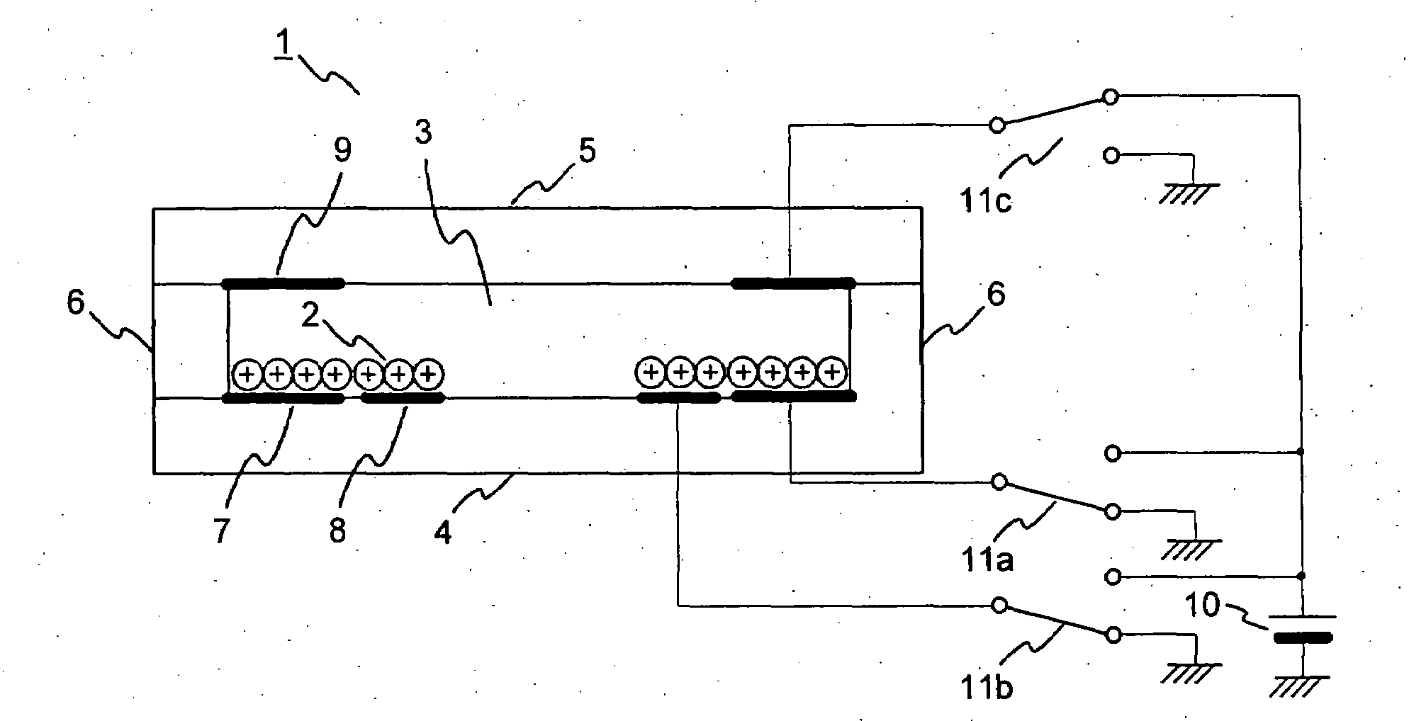
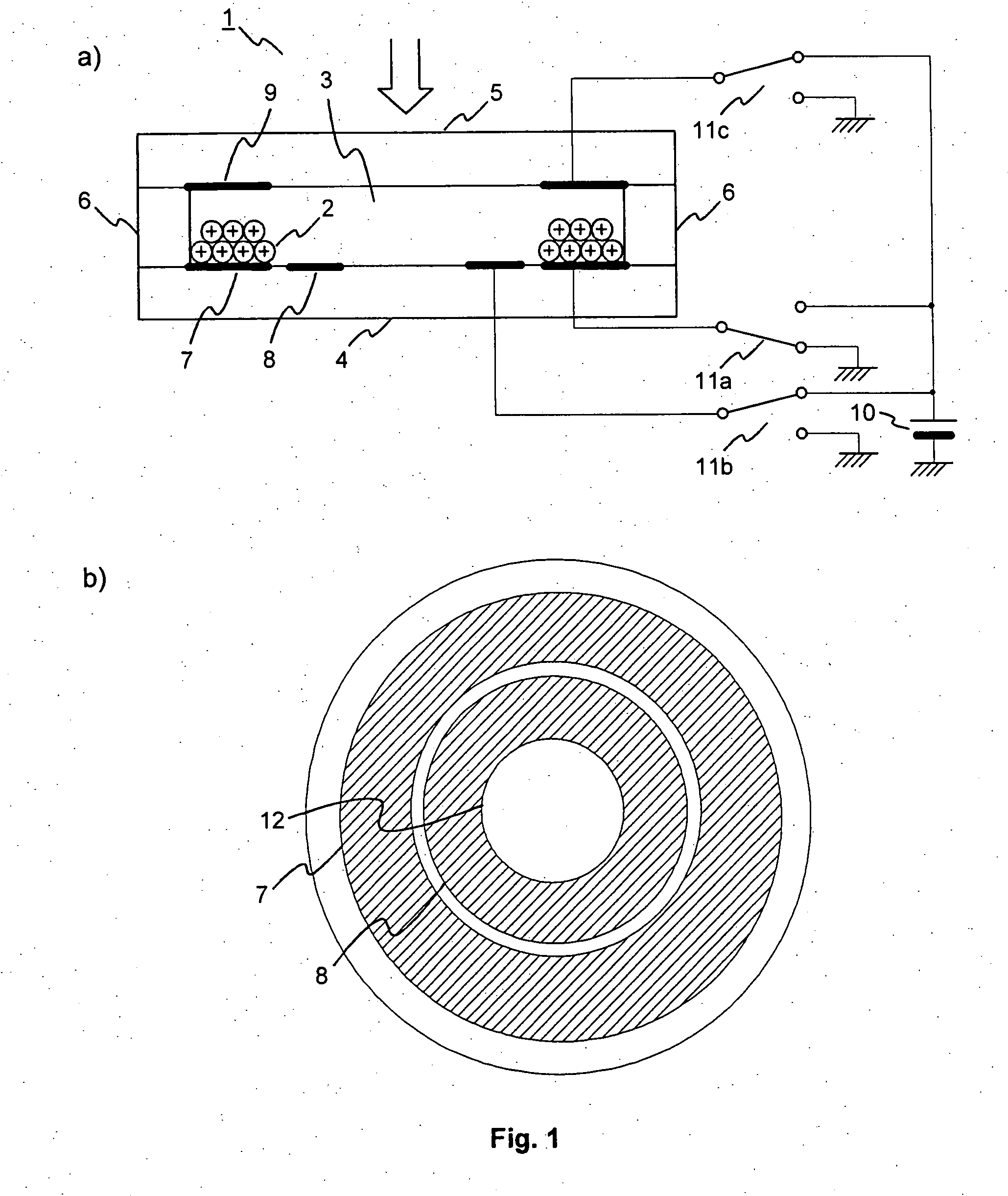
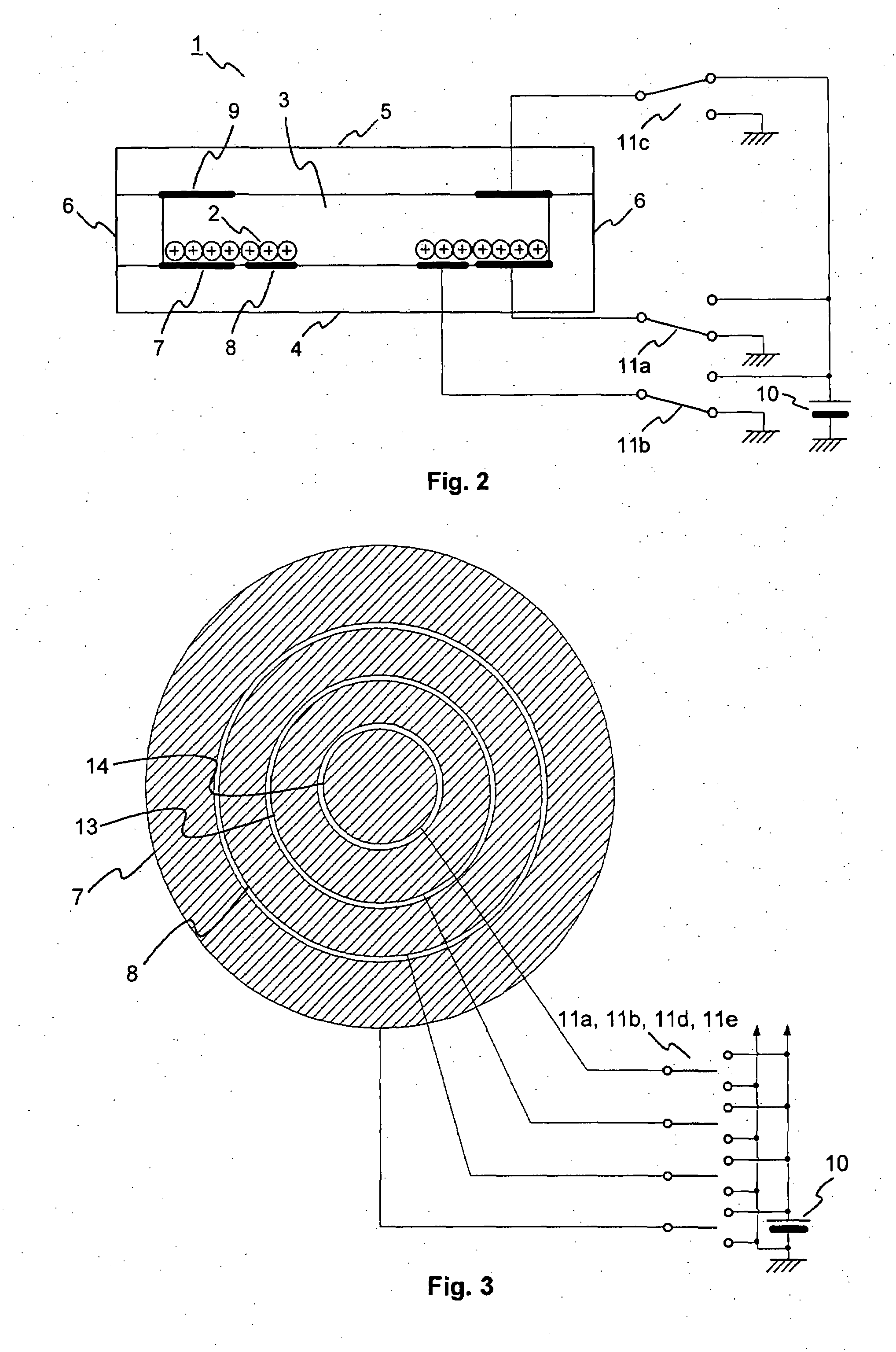
[0023]FIGS. 1 and 2 show the basic concept of a variable iris 1 according to the invention using electrophoretic particles. FIG. 1a) is a side view, FIG. 1b) a top view of the variable iris 1 in its open state, while FIG. 2 is a side view of the variable iris 1 in its (partially) closed state. As can be seen in FIG. 1a), charged opaque particles 2 are confined in a cell 3 composed of transparent substrates 4, 5 and ribs 6. The cell 3 is filled with a liquid. The charged opaque particles 2 have a positive electric charge. The opaque particles 2 are preferably black or gray particles, as this avoids stray light, but particles 2 with any other color can likewise be used. Transparent ring-shaped electrodes 7, 8, 9 are placed on the transparent substrates 4, 5, namely a first electrode 7 and a second electrode 8 on the bottom transparent substrate 4 and a third electrode 9 on the top transparent substrate 5. The first and second ring-shaped electrodes 7, 8 surround a center transparent z...


PUM


Abstract

Variable iris using charged opaque particles The present invention relates to a variable iris using charged opaque particles, and to a method for operating such a variable iris.
According to the invention, the variable iris has a first transparent substrate and a second transparent substrate, which are separated by one or more ribs to form a cell confining charged opaque particles, the first transparent substrate being provided with at least a first electrode and a second electrode both being adapted to be connected to a voltage source for acting on the charged opaque particles, and at least a third electrode adapted to be connected to the voltage source for acting on the charged opaque particles, the voltages applied to the first electrode, the second electrode, and the third electrode being controllable to have the same or opposite signs. The variable iris further has a pulse driver for applying voltage pulses to the electrodes.

Description

FIELD OF THE INVENTION[0001]The present invention relates to a variable iris using charged opaque particles, and to a method for controlling such a variable iris.BACKGROUND OF THE INVENTION[0002]Nowadays lots of digital (still and movie) cameras are available on the market. Different kinds of diaphragms for controlling the amount of light falling onto a photodetector are utilized in lens optics. The most widely used diaphragm is the iris diaphragm. However, this mechanical iris diaphragm has a number of disadvantages. It is not suitable for small lens assemblies, as for example in current small digital cameras, due to the necessary size of the mechanical components. In addition, it is not possible to control the shape of the aperture. As springs and a mechanical movement are used, the iris diaphragm needs maintenance. Finally, this type of diaphragm has a relatively slow response.[0003]To circumvent at least some of the above problems, electronic diaphragms based on liquid crystal e...

Claims


Application Information

Patent Timeline
IPC IPC(8): G06F13/40G02F1/167G02F1/1676G02F1/16761G02F1/1685
CPCG02B5/005H04N5/238G03B9/02G02F1/167G02F1/1685G02F1/1676G02F1/16761H04N23/75
Inventor CHIKAZAWA, YOSHIHARUGOTOH, TOSHIHIKO
Owner MAGNOLIA LICENSING LLC
Why Eureka
Try Eureka