Method and device for catalytic hydrolysis of urea

A urea catalyzed hydrolysis and urea hydrolysis technology, applied in the field of urea catalyzed hydrolysis, can solve problems such as not very mature, and achieve the effects of fast reaction speed, low operating cost and high superiority

Active Publication Date: 2013-11-20
DATANG ENVIRONMENT IND GRP +1
View PDF9 Cites 17 Cited by
  • Summary
  • Abstract
  • Description
  • Claims
  • Application Information

AI Technical Summary

Problems solved by technology

[0006] The reaction speed of catalytic hydrolysis is also fast, the start and stop are fast, and the ene

Method used


Image

  • Method and device for catalytic hydrolysis of urea
  • Method and device for catalytic hydrolysis of urea

Examples


Embodiment 1

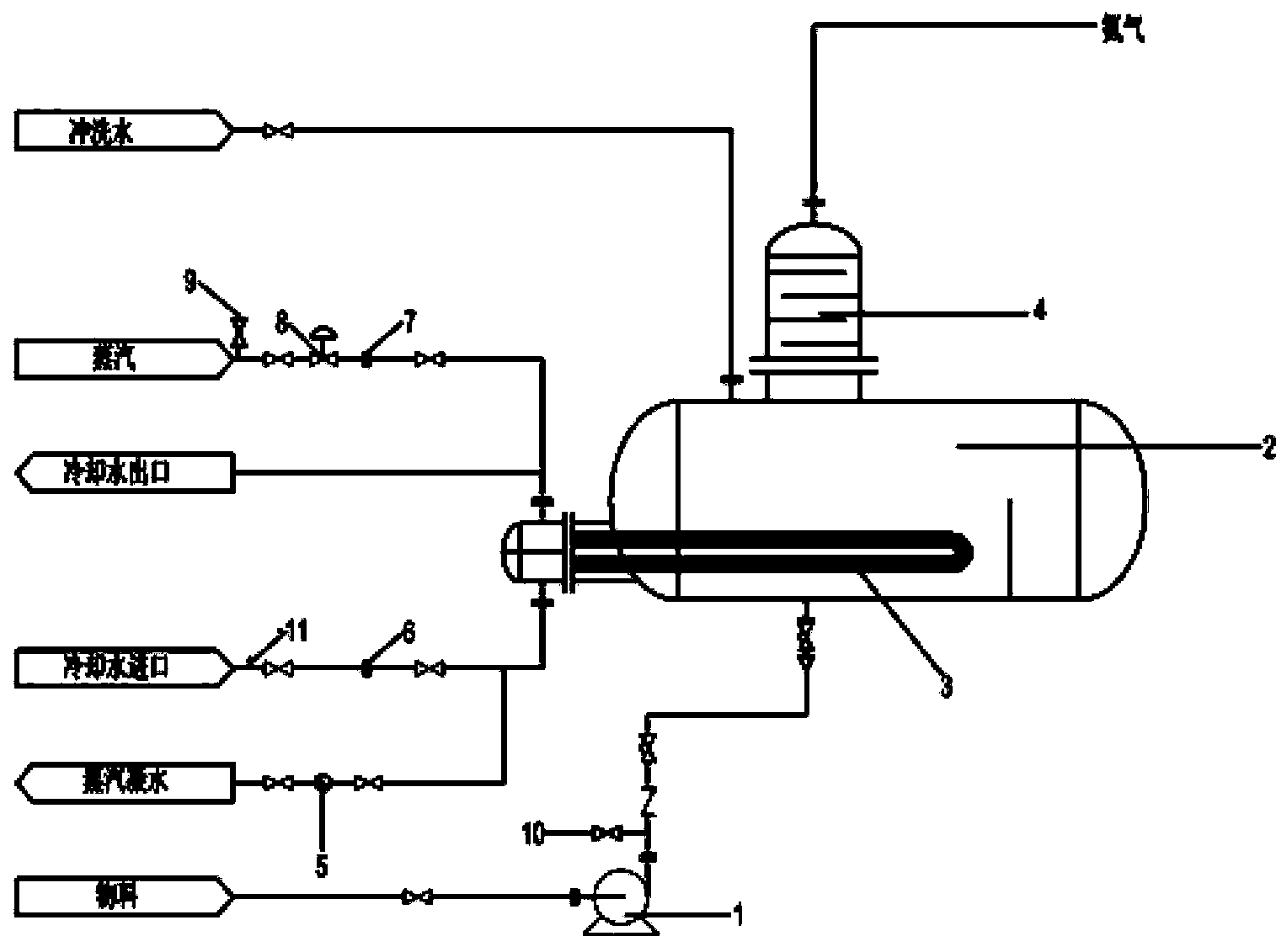
[0038] Urea catalytic hydrolysis device of the present invention, such as figure 1 As shown, it includes: feed pump 1, urea hydrolysis reactor 2, an on-site pressure gauge 10 is provided on the connecting pipeline between feed pump 1 and urea hydrolysis reactor 2, and a steam coil is inserted in the urea hydrolysis reactor 2 3. The steam inlet pipe is connected to the cooling water outlet pipe and connected to the top of the outer side of the steam coil 3. The steam inlet pipe is provided with a flow meter 7, a temperature regulating valve 8 and an on-site pressure gauge 9; the steam outlet pipe and the cooling water The inlet pipe is connected to the bottom of the outer side of the steam coil 3, and a steam trap 5 is provided on the steam outlet pipe, which can make the steam condense and release the condensation heat to be absorbed by the urea solution, saving steam to the greatest extent. A flow meter 6 and a thermometer 11 are provided to indicate the temperature and flow ...

Embodiment 2

[0053] 1) The dry urea powder is stored in the storage bin, transported to the dissolving tank by the screw feeder, the dry urea is dissolved into a 45% mass concentration urea solution with deionized water, and transported to the urea hydrolysis reactor through the feed pump;

[0054] 2) The catalyst diammonium hydrogen phosphate and ammonium dihydrogen phosphate are transported to the urea hydrolysis reactor through the feed pump according to different proportions, reaching 8% of the reactor volume; the urea solution and the catalyst are mixed evenly.

[0055] 3) The urea hydrolysis reactor is heated by means of airtight electric heat tracing. The heating temperature is 160°C and the pressure is 0.7MPa to realize the catalytic hydrolysis of urea.

Embodiment 3

[0057] 1) The dry urea powder is stored in the storage bin, transported to the dissolution tank by the screw feeder, and the dry urea is dissolved into a 50% mass concentration urea solution with deionized water, and transported to the urea hydrolysis reactor through the feed pump;

[0058] 2) The catalyst diammonium hydrogen phosphate and ammonium dihydrogen phosphate are transported to the urea hydrolysis reactor through the feed pump according to different proportions, reaching 10% of the reactor volume; the urea solution and the catalyst are mixed evenly.

[0059] 3) Use steam heating method to heat the urea hydrolysis reactor, heating temperature: 180°C, pressure: 0.8MPa, to realize catalytic hydrolysis of urea.


PUM


Abstract

The invention discloses a method and a device for catalytic hydrolysis of urea. The method comprises the steps: according to different proportions, adding diammonium hydrogen phosphate and ammonium dihydrogen phosphate as catalysts into a urea hydrolysis reactor, sending a urea solution with the mass concentration of 40-50% to the urea hydrolysis reactor, then controlling the temperature of the urea hydrolysis reactor at 150-180 DEG C and the pressure to be 0.6-0.8 MPa, to achieve catalytic hydrolysis of urea. The method and the device have the beneficial effects that: 1) the reaction speed is relatively rapid, and thereby meeting requirements of denitration on ammonia; 2) an ammonia leakage protection system and a pressure, temperature and liquid level high-low automatic control system are added, and the security is also quite high; and 3) the operating cost is low and is half of that of pyrolysis. Therefore, the method and the device for catalytic hydrolysis of urea have relatively high superiority.

Description

technical field [0001] The invention belongs to the technical field of air pollution control, and relates to a method and a device for catalytic hydrolysis of urea. Background technique [0002] Flue gas denitrification refers to the technology for removing the harmful substance NOX contained in the flue gas after high-temperature combustion (including coal-fired boilers, oil-fired gas boilers and some industrial furnaces), including two main technical schools of SCR and SNCR. SCR is the mainstream technology for flue gas denitrification. The so-called SCR technology refers to installing an SCR reactor between the economizer and the air preheater of the boiler, installing a catalyst in the reactor, injecting a reducing agent (ammonia-containing gas) into the flue section before the reactor, reducing agent and NO X The reaction takes place on the surface of the catalyst to remove NO X . [0003] The reducing agent used in SCR flue gas denitrification is fundamentally ammo...

Claims


Application Information

Patent Timeline
IPC IPC(8): C01C1/02
Inventor 彭代军申镇宋云鹏谭效德丁艳军
Owner DATANG ENVIRONMENT IND GRP
Why Eureka
Try Eureka