
Expansion joint seal system with spring centering and ribs with protuberances

a technology of expansion joint and protuberance, which is applied in the direction of roads, buildings, and construction components, can solve the problems of joint damage, seals may become inflexible, fragile, and/or experience cohesive and/or adhesive failure, and are particularly difficult to address

Active Publication Date: 2019-03-07
SCHUL INT COMPANY
View PDF1 Cites 38 Cited by
  • Summary
  • Abstract
  • Description
  • Claims
  • Application Information

AI Technical Summary

Benefits of technology

The present invention provides an expansion joint system with an elastically-compressible core and a flexible member attached to the cover plate and ribs. The ribs pierce the core and are rotatable, allowing for a seamless expansion and contraction of the system. The technical effects include improved flexibility, durability, and aesthetic appearance, making the expansion joint system suitable for a variety of applications such as construction joints and seals.

Problems solved by technology

Moreover, these joints are subject to damage over time.
Most damage is from vandalism, wear, environmental factors and when the joint movement is greater, the seal may become inflexible, fragile or experience cohesive and / or adhesive failure.
This may be particularly difficult to address as the size of the expansion joint increases.
While such foams may take a compression set, limiting the capability to return to the maximum original uncompressed dimension, such foams do permit compression and some return toward to the maximum original uncompressed dimension.
These systems lack the resiliency and seismic movement required in expansion joints.
These systems have been further limited from desirably functioning as a fire-resistant barrier.
Other systems have incorporated cover plates that span the joint itself, often anchored to the concrete or attached to the expansion joint material and which are expensive to supply and install.
These systems sometimes require potentially undesirable mechanical attachment, which requires drilling into the deck or joint substrate.
Cover plate systems that are not mechanically attached rely on support or attachment to the expansion joint, thereby subjecting the expansion joint seal system to continuous compression, expansion and tension on the bond line when force is applied to the cover plate, which shortens the life of the joint seal system.
Unfortunately, these do no properly address vertical shifts—where the substrates become misaligned when the end of one shifts vertically relative to the other or longitudinal shifts between panels.
In such situations, the components attached to the cover plate are likewise rotated or elevated in space causing a pedestrian or vehicular hazard.
The current systems do not adequately address the differences in the coefficient of linear expansion between the cover plate and the substrate or allow for curved joint designs.
The inability of the current art to compensate for the lateral or thermal movement of the cover plate results in failure of attachment to the cover plate or additional pressure being imposed on one half of the expansion joint system and potentially pulling the expansion joint system away from the lower substrate.
Current systems do not sufficiently address the potential impact or shock to the cover plate from vehicular traffic over time or by a snowplow or other.

Method used


Image

  • Expansion joint seal system with spring centering and ribs with protuberances
  • Expansion joint seal system with spring centering and ribs with protuberances
  • Expansion joint seal system with spring centering and ribs with protuberances

Examples


Embodiment Construction

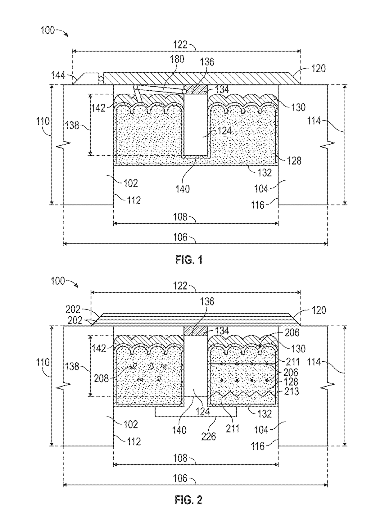
[0038]An expansion joint seal system 100 is provided for imposition in a joint, such that a portion remains above the joint, i.e. partial imposition. The joint is formed of a first substrate 102 and a second substrate 104, which are each substantially co-planar with a first plane 106. The joint is formed as the first substrate 102 is separated, or distant, the second substrate 104 by a first distance 108. The first substrate 102 has a first substrate thickness 110, and has a first substrate end face 112 substantially perpendicular to the first plane 106. Likewise, the second substrate 104 has a second substrate thickness 114, and has a second substrate end face 116 substantially perpendicular to the first plane 106.

[0039]By selection of the properties of its various elements, the expansion joint seal system 100 may provide sufficient fire endurance and movement to obtain at least the minimum certification under fire rating standards. The selection of fire retardant components permit...


PUM

PropertyMeasurementUnit
densityaaaaaaaaaa
densityaaaaaaaaaa
tensile strengthaaaaaaaaaa

Abstract

A system which creates a durable seal between adjacent horizontal panels, including those that may be curved or subject to temperature expansion and contraction or mechanical shear. The durable seal system incorporates a plurality of ribs, a flexible member between the cover plate and the ribs and may incorporate a load transfer plate to provide support to the rib from below, and / or cores of differing compressibilities.

Description

CROSS-REFERENCE TO RELATED APPLICATIONS[0001]This application is a continuation-in-part of U.S. patent application Ser. No. 15 / 890,823 filed Feb. 7, 2018, which is incorporated herein by reference, which is a continuation-in-part of U.S. patent application Ser. No. 15 / 702,211 for “Durable Joint Seal System with Detachable Cover Plate and Rotatable Ribs” filed Sep. 12, 2017, which is incorporated herein by reference, which is a continuation-in-part of U.S. patent application Ser. No. 15 / 649,927 for “Expansion Joint Seal for Surface Contact Applications,” filed Jul. 14, 2017, which is incorporated herein by reference, and which issued Dec. 12, 2017 as U.S. Pat. No. 9,840,814, which is a continuation of U.S. patent application Ser. No. 15 / 062,354 for “Expansion Joint Seal for Surface Contact Applications,” filed Mar. 7, 2016, which is incorporated herein by reference, and which issued Sep. 19, 2017 as U.S. Pat. No. 9,765,486.STATEMENT REGARDING FEDERALLY SPONSORED RESEARCH OR DEVELOPME...

Claims


Application Information

Patent Timeline
Patent Type & Authority Applications(United States)
IPC IPC(8): E01C11/12E01C11/04E04B1/68E01C11/10
CPCE01C11/04E04B1/6812E01C11/126E04B1/6801E01C11/106E04B1/6804E04H9/02
Inventor ROBINSON, STEVEN R.
Owner SCHUL INT COMPANY
Features
  • Generate Ideas
  • Intellectual Property
  • Life Sciences
  • Materials
  • Tech Scout
  • Unparalleled Data Quality
  • Higher Quality Content
  • 60% Fewer Hallucinations
Learn More