Force Measurement System and a Method of Calibrating the Same

a technology of force measurement and force plate, which is applied in the direction of force measurement, force/torque/work measurement apparatus, instruments, etc., can solve the problems of undesirable crosstalk between channels, significant increase in material costs associated with the fabrication of force plates, and elongation of load transducers that utilize an excessive amount of stock materials

Active Publication Date: 2019-03-14
BERTEC
View PDF5 Cites 40 Cited by
  • Summary
  • Abstract
  • Description
  • Claims
  • Application Information

AI Technical Summary

Problems solved by technology

These custom load transducers significantly increase the material costs associated with the fabrication of a force plate.
Also, conventional load transducers often span the full length or width of the force plate component to which they are mounted, thereby resulting in elongate load transducers that utilize an excessive amount of stock material.
However, because the body portion of a typical load transducer has unavoidable machining imperfections, and the strain gages are not perfectly positioned on the body of the load transducer, there is some crosstalk between the channels of the load transducer.
Thus, in such a typical load transducer, there is undesirable crosstalk between the channels.
Moreover, the output of a typical multi-component load transducer is also undesirably affected by the ambient temperature of the environment in which the load transducer is disposed.
For example, the accuracy of a load output signal of a load transducer that is disposed in a space having a high ambient temperature (e.g., a space with a temperature of 140 degrees or more) will be adversely affected by the high ambient temperature.
That is, high ambient temperature will introduce inaccuracies in the load output signal.
Furthermore, the position of the applied load may also adversely affect the accuracy of the output signal of a typical multi-component load transducer.
For example, when the load is applied at a location that is near the periphery of the measurement surface of the load measurement device in which the load transducer is installed, the load output of the load transducer is often less accurate than when the load is applied proximate to the center of the measurement surface of the load measurement device.
As such, the measurement accuracy of a typical load measurement device undesirably varies depending upon the position of the load applied thereto.
However, the global calibration of the force plate can result in unacceptable errors for certain regions of the force plate (e.g., near the edges of the force plate), and can also result in unacceptable errors for force plates having non-standard shapes (e.g., force plates with top plate components having shapes other than a rectangular shape).

Method used


Image

  • Force Measurement System and a Method of Calibrating the Same
  • Force Measurement System and a Method of Calibrating the Same
  • Force Measurement System and a Method of Calibrating the Same

Examples


first embodiment

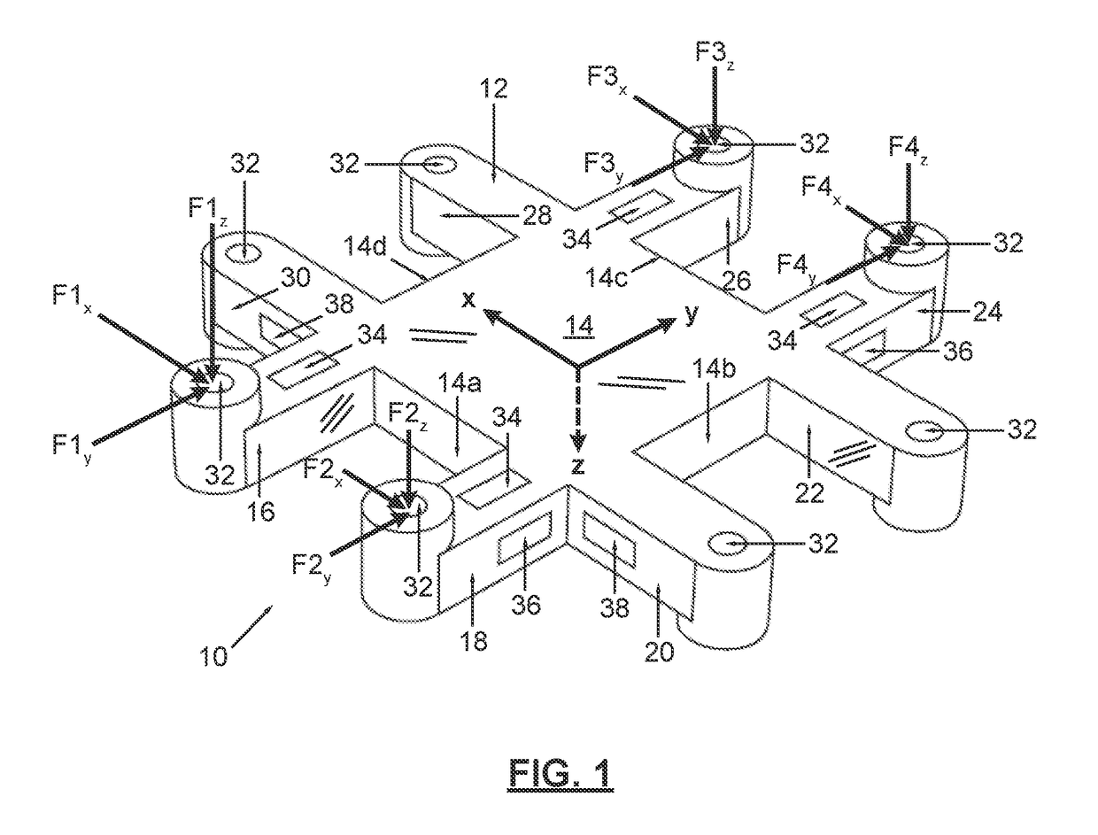
[0036]FIG. 1 is a perspective view of a low profile load transducer, according to the invention;

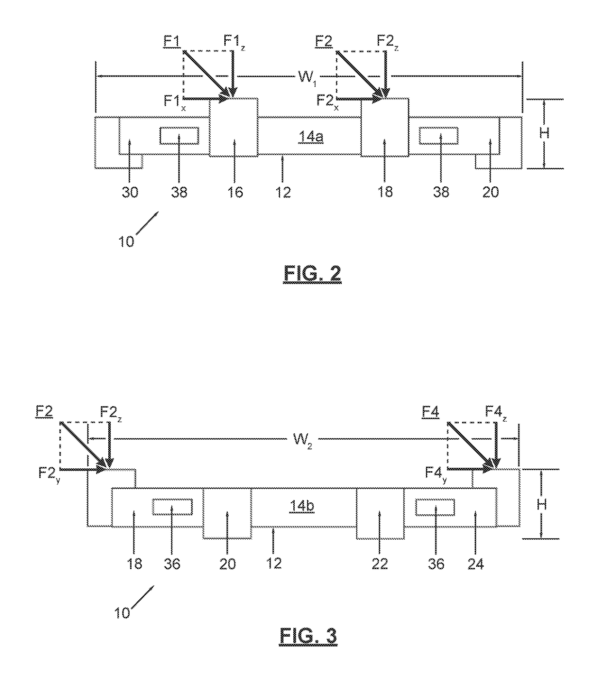
[0037]FIG. 2 is a first side view of the low profile load transducer of FIG. 1, according to the first embodiment of the invention;

[0038]FIG. 3 is a second side view of the low profile load transducer of FIG. 1, according to the first embodiment of the invention;

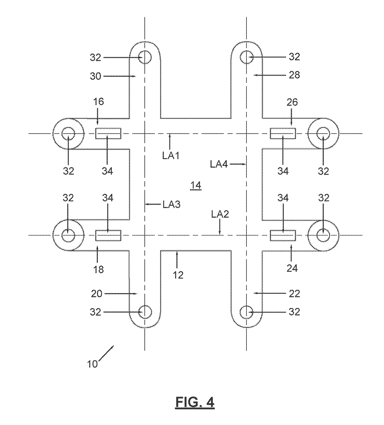
[0039]FIG. 4 is a top view of the low profile load transducer of FIG. 1, according to the first embodiment of the invention;

[0040]FIG. 5 is a block diagram illustrating data manipulation operations carried out by the load transducer data processing system, according to an embodiment of the invention;

second embodiment

[0041]FIG. 6 is a perspective view of a low profile load transducer, according to the invention;

[0042]FIG. 7 is a first side view of the low profile load transducer of FIG. 6, according to the second embodiment of the invention;

[0043]FIG. 8 is a second side view of the low profile load transducer of FIG. 6, according to the second embodiment of the invention;

[0044]FIG. 9 is a top view of the low profile load transducer of FIG. 6, according to the second embodiment of the invention;

third embodiment

[0045]FIG. 10 is a perspective view of a low profile load transducer, according to the invention;

[0046]FIG. 11 is a first side view of the low profile load transducer of FIG. 10, according to the third embodiment of the invention;

[0047]FIG. 12 is a second side view of the low profile load transducer of FIG. 10, according to the third embodiment of the invention;

[0048]FIG. 13 is a top view of the low profile load transducer of FIG. 10, according to the third embodiment of the invention;

[0049]FIG. 14 is a bottom view of the low profile load transducer of FIG. 10, according to the third embodiment of the invention;


PUM

PropertyMeasurementUnit
force measurementaaaaaaaaaa
forceaaaaaaaaaa
pressureaaaaaaaaaa

Abstract

A force measurement system is disclosed herein. The force measurement system includes a force measurement assembly and a data processing device operatively coupled to the force measurement assembly. In one or more embodiments, the data processing device is configured to reference a stored global calibration matrix for the force measurement assembly, to determine a location of an applied load on the surface of the force measurement assembly using the stored global calibration matrix, to assign the applied load to one or more of a plurality of different load regions based upon the location of the applied load, and to compute one or more output forces or moments of the applied load using stored local calibration information for the one or more of the plurality of different load regions. A method of calibrating a force measurement system is also disclosed herein.

Description

CROSS-REFERENCE TO RELATED APPLICATIONS[0001]This is a continuation-in-part of U.S. Nonprovisional patent application Ser. No. 15 / 721,951, entitled “Load Transducer System”, filed on Oct. 1, 2017; which is a continuation-in-part of U.S. Nonprovisional patent application Ser. No. 15 / 224,419, entitled “Load Transducer and Force Measurement Assembly Using the Same”, filed on Jul. 29, 2016, now U.S. Pat. No. 9,778,119; which is a continuation-in-part of U.S. Nonprovisional patent application Ser. No. 14 / 714,797, entitled “Load Transducer and Force Measurement Assembly Using the Same”, filed on May 18, 2015, now U.S. Pat. No. 9,404,823; which is a continuation-in-part of U.S. Nonprovisional patent application Ser. No. 14 / 158,809, entitled “Low Profile Load Transducer”, filed on Jan. 18, 2014, now U.S. Pat. No. 9,032,817; and further claims the benefit of U.S. Provisional Patent Application No. 61 / 887,357, entitled “Low Profile Load Transducer”, filed on Oct. 5, 2013, the disclosure of ea...

Claims


Application Information

Patent Timeline
Patent Type & Authority Applications(United States)
IPC IPC(8): G01L5/16G01L25/00
CPCG01L5/16G01L25/00G01L1/2281G01L25/003G01L5/1627G01L5/169
Inventor BERME, NECIPGHASSAB, SASANOBER, JAN JAKUB
Owner BERTEC
Why Eureka
Try Eureka