El element and method for manufacturing el element
a technology of el element and manufacturing method, applied in the field of el element, can solve the problems of difficult to apply upconversion utilizing tta to devices, and difficult to achieve high efficiency, and achieve the effect of high-efficiency triplet-triplet annihilation
- Summary
- Abstract
- Description
- Claims
- Application Information
AI Technical Summary
Benefits of technology
Problems solved by technology
Method used
Image

Examples
first embodiment
[0027]An embodiment of the disclosure will be described in detail below with reference to FIGS. 1 to 3.
Configuration of EL Light-Emitting Device
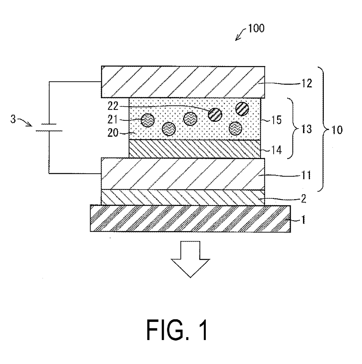
[0028]FIG. 1 is a cross-sectional view of an EL light-emitting device according to the present embodiment.
[0029]An EL light-emitting device 100 has a configuration in which a transparent substrate 1, a reflective electrode 2, and an EL element 10 are provided in this order. Note that it is preferable that a sealing film (not illustrated) for sealing the EL element 10 between the substrate 1 and the sealing film be provided. The substrate 1 may be, for example, a glass substrate.
[0030]The EL element 10 has a configuration in which a first electrode 11, an EL layer 13, and a second electrode 12 are provided in this order from the reflective electrode 2-side. The first electrode 11 is a positive electrode, and the second electrode 12 is a negative electrode. The first electrode 11 and the second electrode 12 are provided to face each other, bet...
second embodiment
[0065]In the following, another embodiment of the disclosure will be described with reference to FIG. 4. Note that members having the same function as the members stated in the embodiment above are appended with the same reference signs for the sake of description, and the description thereof is omitted.
[0066]FIG. 4 is a cross-sectional view of an EL light-emitting device according to the present embodiment.
[0067]An EL light-emitting device 200, according to the present embodiment, has the same configuration as the EL light-emitting device 100 according to the first embodiment except that an EL layer 113 is included instead of the EL layer 13 of the EL light-emitting device 100 of the first embodiment. The EL layer 113 includes a film thickness adjustment layer 17 (partition layer) and a green-light-emitting layer 16.
[0068]The EL layer 113 of the EL light-emitting device 200 has a configuration in which the hole injection layer 14, the green-light-emitting layer 16 (second light-emi...
third embodiment
[0078]In the following, another embodiment of the disclosure will be described with reference to FIG. 5. Note that members having the same function as the members stated in the embodiment above are appended with the same reference signs for the sake of description, and the description thereof is omitted.
[0079]FIG. 5 is a cross-sectional view of an EL light-emitting device according to the present embodiment.
[0080]An EL light-emitting device 300, according to the present embodiment, includes an EL element 210. The EL light-emitting device 300 has the same configuration as the EL light-emitting device 100 according to the first embodiment except that the EL element 210 includes, instead of the second electrode 12 of the EL light-emitting device 100 of the first embodiment, a second electrode 212, which is transparent or semitransparent.
[0081]When a voltage is applied between the first electrode 11 and the second electrode 212, positive holes are injected into the EL layer 13 from the ...
PUM
 Abstract
Description
Claims
Application Information
 - R&D
- Intellectual Property
- Life Sciences
- Materials
- Tech Scout
- Unparalleled Data Quality
- Higher Quality Content
- 60% Fewer Hallucinations
Browse by: Latest US Patents, China's latest patents, Technical Efficacy Thesaurus, Application Domain, Technology Topic, Popular Technical Reports.
© 2025 PatSnap. All rights reserved.Legal|Privacy policy|Modern Slavery Act Transparency Statement|Sitemap|About US| Contact US: help@patsnap.com