Electric braking system and operation method thereof

a technology of electric brakes and electric braking, which is applied in the direction of braking systems, vehicle sub-unit features, braking components, etc., can solve the problems of hindering affecting the safety of passengers, etc., and achieves the effect of effective braking, facilitating the driving stability of the vehicle, and stably generating high braking pressur

Active Publication Date: 2019-04-04
HL MANDO CORP
View PDF10 Cites 8 Cited by
  • Summary
  • Abstract
  • Description
  • Claims
  • Application Information

AI Technical Summary

Benefits of technology

[0013]The present disclosure also provides an electronic braking system and operation method thereof, capable of effectively performing braking in various operation situations.
[0014]The present disclosure also provides an electronic braking system and operation method thereof, capable of facilitating driving stability of the vehicle.
[0015]The present disclosure also provides an electronic braking system and operation method thereof, capable of stably generating high braking pressure.
[0016]The pre

Problems solved by technology

While the electronic braking system may implement various complicated braking operations because it is electrically operated and controlled, it might threaten the safety of passengers if technical problems occur in the electric parts of the vehicle and might fail to stably create the hydraulic pressure for braking.
In other words, in the abnormal operation mode of the electronic braking system, as the driver appli

Method used


Image

  • Electric braking system and operation method thereof
  • Electric braking system and operation method thereof
  • Electric braking system and operation method thereof

Examples


Embodiment Construction

[0052]Reference will now be made in detail to embodiments, examples of which are illustrated in the accompanying drawings. Embodiments as will be described 10 below are suggested to fully deliver an idea of the present disclosure to ordinary skilled people in the art. The present disclosure may not be limited thereto but may be implemented in any other forms. In the drawings, well-known or unrelated components may be omitted for clarity and conciseness, and some components may be exaggerated in terms of their dimensions for better understanding.

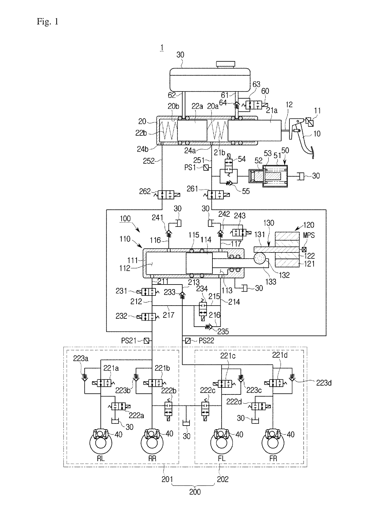
[0053]FIG. 1 is a hydraulic circuit diagram illustrating an electronic braking system 1, according to an embodiment of the present disclosure.

[0054]Referring to FIG. 1, the electronic braking system 1 may include a master cylinder 20 configured to pressurize and discharge a pressure medium, such as brake oil contained inside in response to a pedal effort on a brake pedal 10, a reservoir 30 linked to the master cylinder 20 and storing the pres...


PUM


Abstract

Disclosed is an electronic braking system and operation method thereof. The electronic braking system and operation method thereof includes a hydraulic pressure supplier configured to create hydraulic pressure by moving a hydraulic piston based on an electric signal output to correspond to displacement of a brake pedal, and a hydraulic controller configured to control hydraulic pressure of a pressure medium applied to each wheel cylinder, and performs normal operation mode, abnormal operation mode, regenerative braking mode, and check mode by controlling a plurality of valves equipped in the hydraulic controller.

Description

CROSS-REFERENCE TO RELATED APPLICATION[0001]This application is based on and claims priority under 35 U. S. C. §119 to Korean Patent Application No. 10-2017-0127510 filed on Sep. 29, 2017, in the[0002]Korean Intellectual Property Office, the disclosure of which is incorporated herein by reference in its entirety.BACKGROUND1. Field of the Invention[0003]The present disclosure relates to an electric braking system and operation method thereof, and more particularly, to an electric braking system and operation method thereof, which generates braking force using an electric signal corresponding to the displacement of the brake pedal.2. Discussion of Related Art[0004]It is essential for vehicles to be equipped with a braking system to perform braking, and various types of braking systems are proposed for the safety of drivers and passengers.[0005]The conventional braking system mainly employs a method of using a booster mechanically coupled to the brake pedal to apply hydraulic pressure ...

Claims


Application Information

Patent Timeline
IPC IPC(8): B60T13/68B60T13/14B60T7/04B60T13/66
CPCB60T13/686B60T13/145B60T7/042B60T13/662B60T8/4081B60T13/745B60T2270/404B60T13/148B60T2270/60B60T2220/04B60Y2400/81B60Y2300/18125B60Y2400/306
Inventor JEONG, HYOJIN
Owner HL MANDO CORP
Why Eureka
Try Eureka