
Electronic brake system and control method thereof

a technology of electronic brakes and control methods, applied in the direction of braking systems, vehicle sub-unit features, braking components, etc., can solve the problems of hydraulic pressure leakage, hydraulic pressure drop, etc., and achieve the effect of effective braking

Active Publication Date: 2020-06-30
HL MANDO CORP
View PDF20 Cites 4 Cited by
  • Summary
  • Abstract
  • Description
  • Claims
  • Application Information

AI Technical Summary

Benefits of technology

This patent is about a new electronic braking system and its control method that can detect if there is a problem with the hydraulic system and still work effectively to stop the car.

Problems solved by technology

Accordingly, when a failure occurs in the connection of the one of the chambers, problems may occur during normal braking as well as during emergency braking, and there is a possibility that the efficiency of the hydraulic pressure supply apparatus may decrease during ABS control.
Further, the electronic control unit may determine that the hydraulic pressure is leaked when the pressure received from the first hydraulic passage pressure sensor or the second hydraulic passage pressure sensor is lower than a minimum pressure preset in each of the first and second hydraulic pressure circuits.

Method used


Image

  • Electronic brake system and control method thereof
  • Electronic brake system and control method thereof
  • Electronic brake system and control method thereof

Examples


Embodiment Construction

[0026]Hereinafter, embodiments of the present disclosure will be described in detail with reference to the accompanying drawings. The following embodiments are provided to fully convey the spirit of the present disclosure to a person having ordinary skill in the art to which the present disclosure belongs. The present disclosure is not limited to the embodiments shown herein but may be embodied in other forms. The drawings are not intended to limit the scope of the present disclosure in any way, and the size of components may be exaggerated for clarity of illustration. Like reference numerals designate like elements throughout the specification.

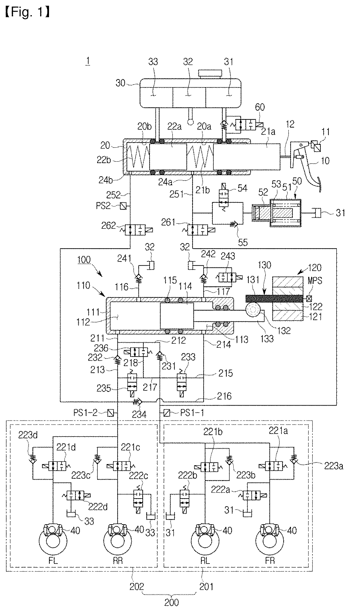
[0027]FIG. 1 is a hydraulic circuit diagram showing a non-braking state of an electronic brake system according to an embodiment of the present disclosure.

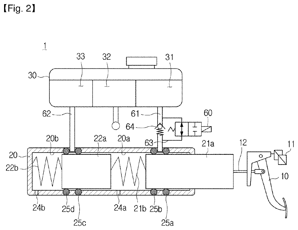
[0028]Referring to FIG. 1, an electronic brake system 1 typically includes a master cylinder 20 for generating a hydraulic pressure, a reservoir 30 coupled to an upper portion of the master...


PUM


Abstract

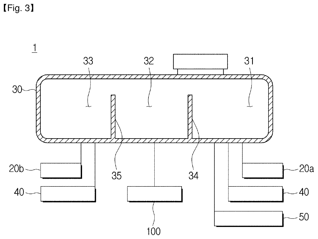
Disclosed are an electronic brake system and a control method thereof. The electronic brake system and the control method thereof include a reservoir in which oil is stored; a master cylinder connected to the reservoir and discharging oil according to a pedal effort of a brake pedal; a hydraulic pressure supply apparatus which is operated by an electrical signal corresponding to the pedal effort to generate a hydraulic pressure; a hydraulic control unit configured to be separated into a first hydraulic circuit and a second hydraulic circuit so as to transmit the hydraulic pressure discharged from the hydraulic pressure supply apparatus to wheel cylinders provided on two wheels, respectively; and a first hydraulic passage pressure sensor for sensing the hydraulic pressure of the first hydraulic circuit and a second hydraulic passage pressure sensor for sensing the hydraulic pressure of the second hydraulic circuit, the reservoir includes a first reservoir chamber connected to recover oil dumped from the first hydraulic circuit, a second reservoir chamber connected to supply oil to the hydraulic pressure supply apparatus, and a third reservoir chamber connected to recover oil dumped from the second hydraulic circuit, and the first reservoir chamber and the third reservoir chamber are separately provided.

Description

CROSS-REFERENCE TO RELATED APPLICATION(S)[0001]This application is based on and claims priority under 35 U.S.C. § 119 to Korean Patent Application No. 10-2017-0063393, filed on May 23, 2017 in the Korean Intellectual Property Office, the disclosure of which is incorporated by reference herein in its entirety.BACKGROUND1. Technical Field[0002]The present disclosure relates to an electronic brake system and a control method thereof, and more particularly to an electronic brake system for generating a braking force in response to an electrical signal and detecting a leakage occurring in a hydraulic circuit and effectively braking the same.2. Description of the Related Art[0003]A vehicle is essentially equipped with a brake system for braking. Recently, various types of systems have been proposed for obtaining a more powerful and stable braking force.[0004]Examples of the brake system include an anti-lock brake system (ABS) that prevents slippage of wheels during braking, a brake tracti...

Claims


Application Information

Patent Timeline
Patent Type & Authority Patents(United States)
IPC IPC(8): B60T8/40B60T7/04B60T17/22B60T13/66B60T11/26B60T8/00B60T13/68B60T13/14B60T13/74B60T8/172B60T8/171
CPCB60T8/00B60T13/142B60T8/4081B60T13/662B60T13/745B60T7/042B60T17/22B60T13/686B60T8/172B60T8/171B60T13/146B60T11/26B60T17/221B60T2270/403B60T2270/82B60T2270/402B60T2220/04B60T13/14B60Y2400/306B60Y2400/81
Inventor JEONG, HYOJIN
Owner HL MANDO CORP
Learn More