
Lightweight grip

Inactive Publication Date: 2019-04-25
EATON INTELLIGENT POWER LIMITED
View PDF1 Cites 2 Cited by
  • Summary
  • Abstract
  • Description
  • Claims
  • Application Information

AI Technical Summary

Benefits of technology

The patent text describes a new design for a grip that enhances shock absorption and comfort for the user. The design includes through-wall cavities that have been shaped to provide desired results in certain areas of the grip. These cavities can vary in size, shape, and location to provide more cushioning or comfort in one region of the grip, while also improving traction in another region. Overall, this design helps to make the grip more comfortable and comfortable to use.

Problems solved by technology

This can require an amount of material that adds weight to the implement and a resultant increase in cost for the material.

Method used


Image

  • Lightweight grip
  • Lightweight grip
  • Lightweight grip

Examples


Embodiment Construction

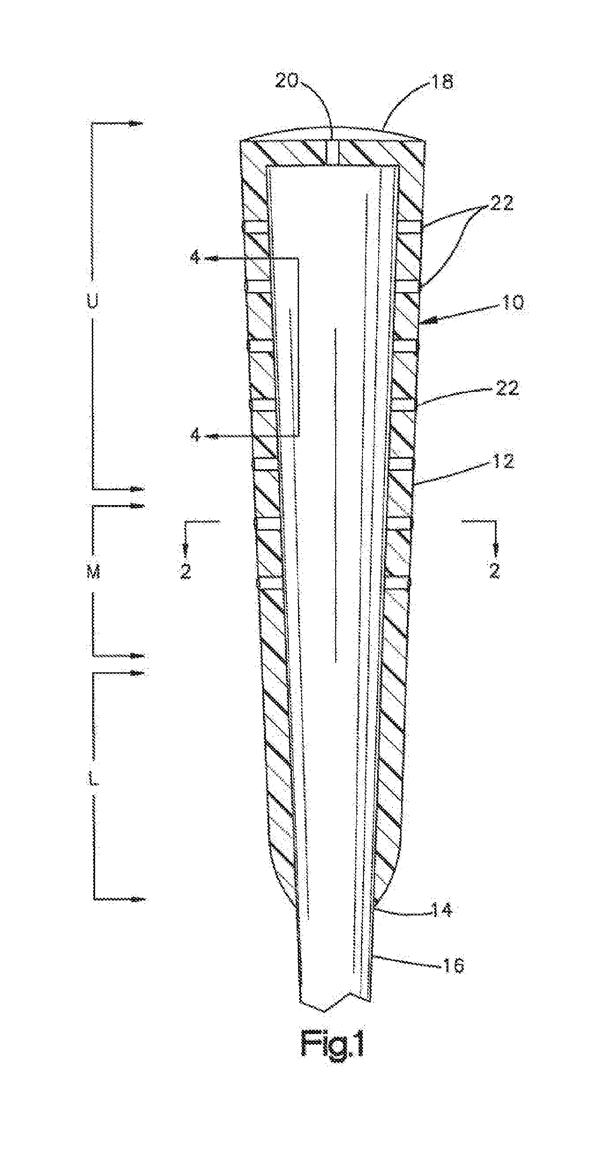
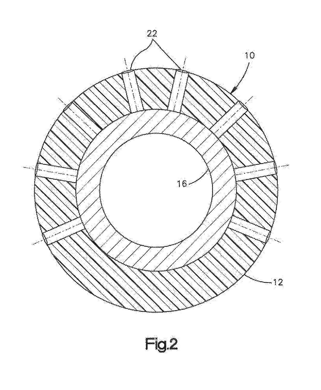
[0015]Referring to the Figures which are not intended to limit the present disclosure and where like numerals designate like or similar features throughout the several views, and first in particular to FIG. 1, there is shown one version of the lightweight flexible grip of the present disclosure generally designated as 10. Grip 10 is an elongated flexible tubular member 12 formed of an elastomeric, rubber, or thermoplastic material, or combinations thereof, and has an open end 14 to a hollow interior which is adapted to have received therein a handle or shaft 16 of an implement, such as a shock imparting implement as an example, which in the illustrated version of the Figures comprises a tubular shaft for a golf club. It should be understood that the present disclosure finds application to any hand grip and should not be limited to just golf club grips. The grip 10 has a substantially closed end 18 opposite the open end 14 referred to herein as the butt end of the grip. The butt end ...


PUM


Abstract

A lightweight flexible grip for a shock imparting implement having a plurality of through the wall cavities. The through the wall cavities may have any shape or form and be located in any desired arrangement and location on the grip. The present disclosure is particularly suited as a hand grip for a sporting implement like a lightweight golf club grip having good traction, comfort, and hand feel.

Description

CROSS-REFERENCE TO RELATED APPLICATIONS[0001]This application claims priority to co-pending application U.S. Ser. No. 62 / 575,564, filed Oct. 23, 2017, in the name of Stephen James Davis for a “Lightweight Grip”, which is incorporated by reference herein in its entirety.BACKGROUND[0002]The present disclosure relates in general to hand grips, and more particularly to lightweight grips of the type employed with shock imparting implements, for example, golf clubs, tennis racquets, or similar sport implements, or other types of shock imparting implements such as, for example, hammers or axes. The present disclosure may be employed in any application that requires a hand grip including without limitation motorcycles, all-terrain vehicles, jet skis, or personal watercrafts.[0003]Such grips are typically formed of molded rubber or an elastomer in tubular form with one substantially closed end and an opposite open end. The open end receives the handle or shaft of the shock imparting implemen...

Claims


Application Information

Patent Timeline
IPC IPC(8): B25G1/10A63B53/14A63B49/08A63B60/54A63B60/50
CPCB25G1/102A63B53/14A63B49/08A63B60/54A63B60/50A63B2209/00B25G1/01A63B2071/0694A63B60/18A63B60/14A63B60/10
Inventor DAVIS, STEPHEN JAMES
Owner EATON INTELLIGENT POWER LIMITED
Learn More