
Spacer for snowboard

a technology for spacers and snowboards, applied in snowboard bindings, sports apparatus, transportation and packaging, etc., can solve the problems of good damping and shock absorption, and achieve the effect of neither rigidity, flexibility nor geometrical shap

Inactive Publication Date: 2006-06-08
SHAUN PALMER
View PDF7 Cites 11 Cited by
  • Summary
  • Abstract
  • Description
  • Claims
  • Application Information

AI Technical Summary

Benefits of technology

[0005] It is an objective of the present invention to provide an improved spacer for a snowboard which is compatible with several bindings and snowboards known from the state of the art. It is a further objective of the invention to provide a spacer which absorbs and dampens in an improved way shocks and vibrations as they occur while riding a snowboard. It is also an objective of the present invention to provide a spacer which does not negatively influence the snowboard, neither the stiffness, flexibility nor the geometrical shape. It is still a further objective of the present invention to provide a simplified mounting mechanism to connect different bindings with a snowboard without negative loads and forces influencing the snowboard and it's hard points (e.g. tapholes).
[0007] To achieve an optimized absorption of vibrations and shocks while riding, the at least one lateral part comprises at least one region made of a first material and at least one region made of a second material having in general different material constants such as density and elastic modulus then the first material. The first and the second material preferably are out of the group of injection mouldable or pressable plastic or metallic materials. By proper choosing the different density and elastic modulus of the materials combined in a lateral part, best performance and damping is achieved. To obtain optimized results for damping the several materials are preferably arranged penetrating each other three-dimensional. This can be well achieved e.g. by injection moulding the first material into a first cavity and in a second step injection moulding the second material in a second cavity around the first material. Specific results regarding damping and shock absorption are obtained by using materials which are combinable (forming a compound). Different results are obtained by using materials which are not combinable (which are not forming a compound). Preferred materials are Polycarbonate, Polyamide, Polyurethane, Rubber and elastomeric Material in general). These materials are joined together by mechanical connection such as an undercut. The hardness of a soft component is preferably below 60 to 70 shore and the hardness of a hard component is preferably above 60 to 70 shore. A tight connection is achieved if the material injected first is forming part of the mould for the material injected second. Due to the friction which occurs along the interface between the different material components which are not combinable very good damping and shock absorption is obtainable. The ability to absorb shock and vibration is adjustable by the relative and absolute thickness of the material.
[0010] The at least one central and the at least one lateral part of the spacer are in an active combination with the snowboard and / or with the snowboard binding and / or with the snowboard boot, so that the forces are optimally transmitted between their point of origin and their point of effect. As a result of the locating of the spacer in the region of the binding plate, the bearing area for the snowboard boots, particularly in the case of narrow snowboards or snowboards having surface indentations, is purposefully enlarged. The distance between the snowboard boot and the snowboard is increased in an advantageous manner. This has the effect of a better load introduction into the snowboard and / or into the snowboard boots and, especially in the case of making curves, makes a better build-up of pressure between the edges and the substratum possible. Short load paths are preferred.

Problems solved by technology

Due to the friction which occurs along the interface between the different material components which are not combinable very good damping and shock absorption is obtainable.

Method used


Image

  • Spacer for snowboard
  • Spacer for snowboard
  • Spacer for snowboard

Examples


Embodiment Construction

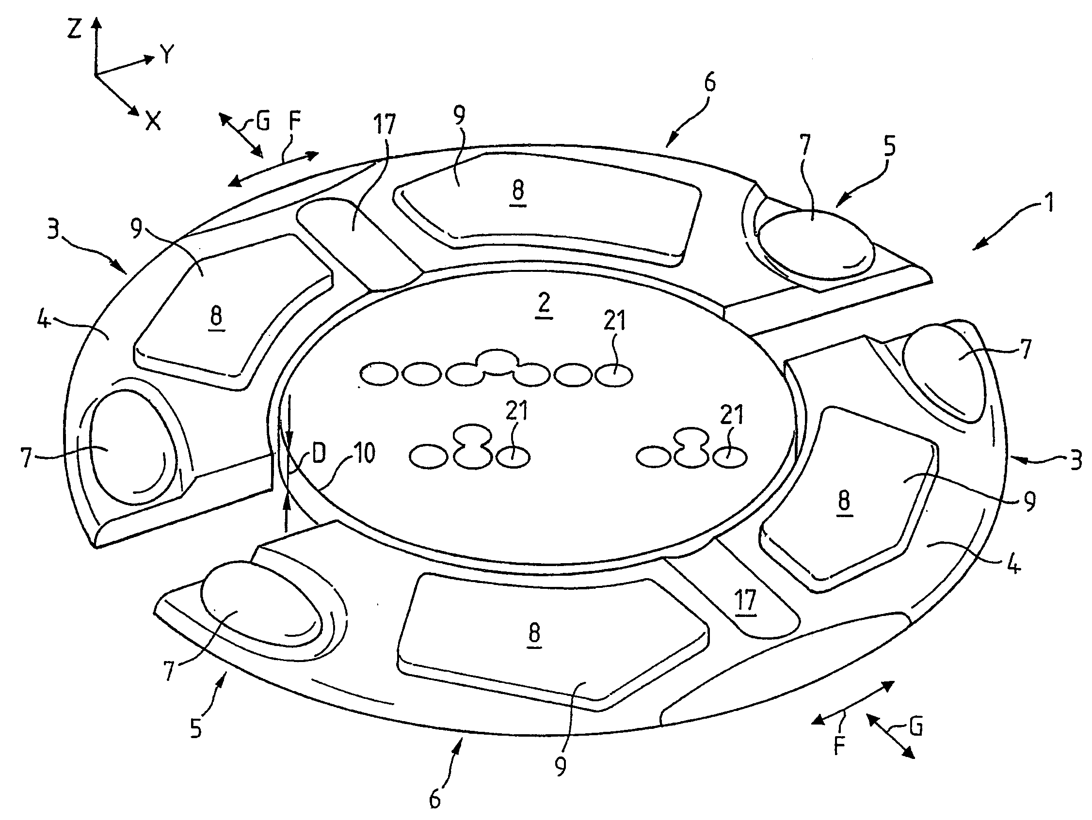
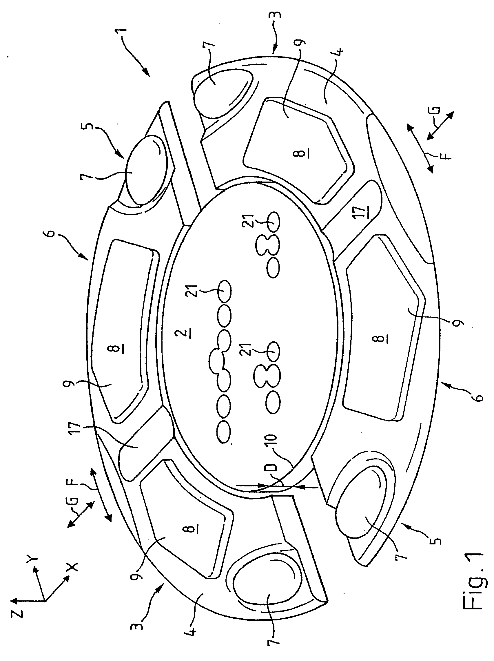
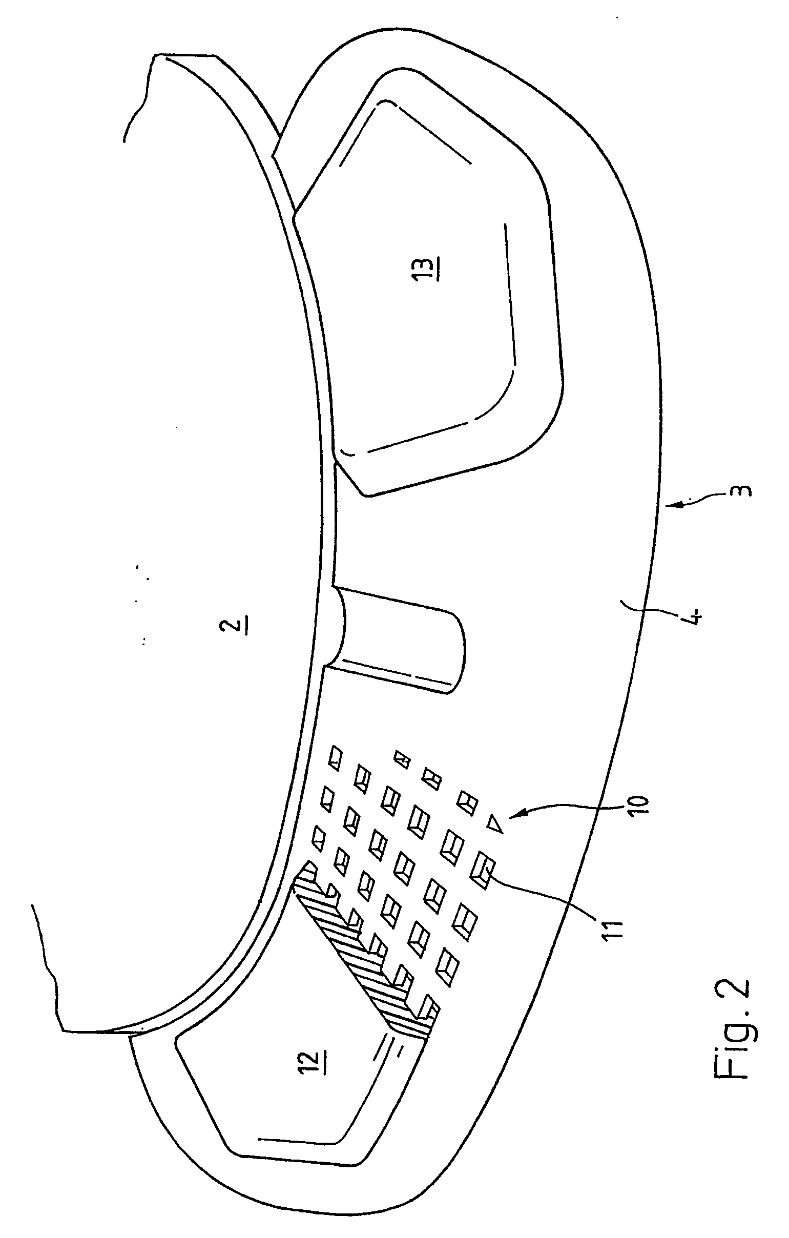
[0021]FIG. 1 illustrates a first embodiment of a spacer 1 in a perspective view. The spacer 1 comprises a centre part 2 and two sickle shaped lateral parts 3 which are arranged adjacent to the centre part 2 adjustable radially and tangentially (arrows F, G) with respect to the centre part 2 in a certain distance such that they are adoptable to the width of a snowboard (not displayed). The horizontal projection of the centre part 4 of this embodiment is round, but may be different, if appropriate. The horizontal projection of the lateral parts 3 is essentially sickle shaped and is corresponding along the inner side with the edge 10 of the centre part 2. The lateral parts 3 have a dual density construction comprising two materials with different material constants. A first material is forming a first part 4. Arranged at a first and a second specific location 5, 6 first and second pads 7, 8 are visible made of a second, in this embodiment elastomeric, material having a lower modulus of...


PUM


Abstract

The invention is directed to an improved spacer (1) with at least one centre part (2) and at least one lateral part (3) comprising at least two different materials. The at least one lateral part serves as a load transfer and distribution mean between one of a tip or a heel of a snowboard boot (40) and a snowboard (20).

Description

FIELD OF THE INVENTION [0001] The invention presented herein relates to an improved spacer for snowboards. DESCRIPTION OF RELATED ART [0002] The inventors of the invention described herein are also the inventors of the spacer described in the U.S. Pat. No. 6,505,841 (from now on US'841). As described in US'841 it is important when riding snowboards, that the contact between the snowboard and the snowboard boot is as direct as possible so that the rider is immediately in a position to react to the movements of the snowboard and can apply the steering forces as efficiently as possible. Long indirect load paths are disadvantageous. The distance holders and binding plates customary today are very rigid and permit practically no deformations. This, in turn, leads to the fact that the elastic characteristic of a snowboard is lastingly and negatively affected with a directly mounted binding plate. [0003] Various snowboard bindings are known in the art. In the document PCT / US98 / 06773, for e...

Claims


Application Information

Patent Timeline
Patent Type & Authority Applications(United States)
IPC IPC(8): B62B13/00B62B15/00A63C10/14A63C10/18A63C10/20A63C10/26A63C10/28
CPCA63C10/14A63C10/18A63C10/20A63C10/26A63C10/285
Inventor KUNZ, JURGMARTIN, PETER
Owner SHAUN PALMER
Learn More