System And Method For Controlling A Digital Micromirror Device (DMD) System To Generate An Image

Active Publication Date: 2009-02-05
TEXAS INSTR INC
View PDF6 Cites 10 Cited by
  • Summary
  • Abstract
  • Description
  • Claims
  • Application Information

AI Technical Summary

Benefits of technology

[0004]In accordance with the present invention, disadvantages and problems associ

Problems solved by technology

The transitioning light may yield undesirable artifacts, so the amplitude modu

Method used


Image

  • System And Method For Controlling A Digital Micromirror Device (DMD) System To Generate An Image
  • System And Method For Controlling A Digital Micromirror Device (DMD) System To Generate An Image
  • System And Method For Controlling A Digital Micromirror Device (DMD) System To Generate An Image

Examples


Example

DETAILED DESCRIPTION OF THE DRAWINGS

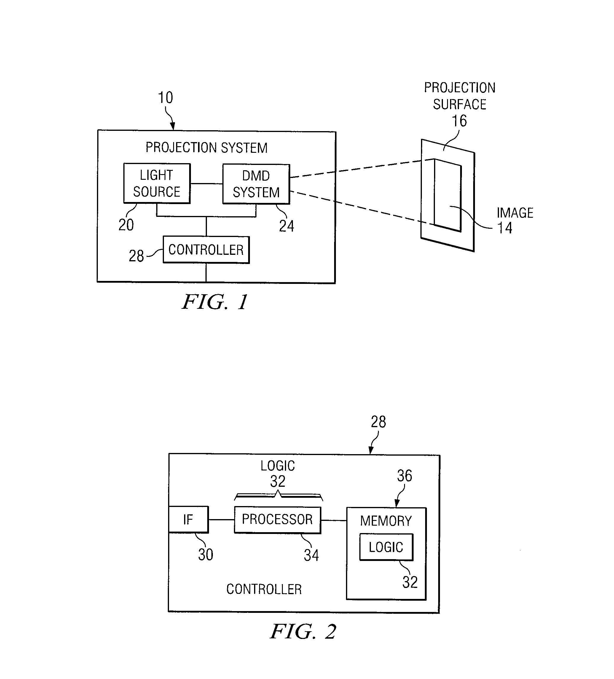
[0013]Embodiments of the present invention and its advantages are best understood by referring to FIGS. 1 through 4 of the drawings, like numerals being used for like and corresponding parts of the various drawings.

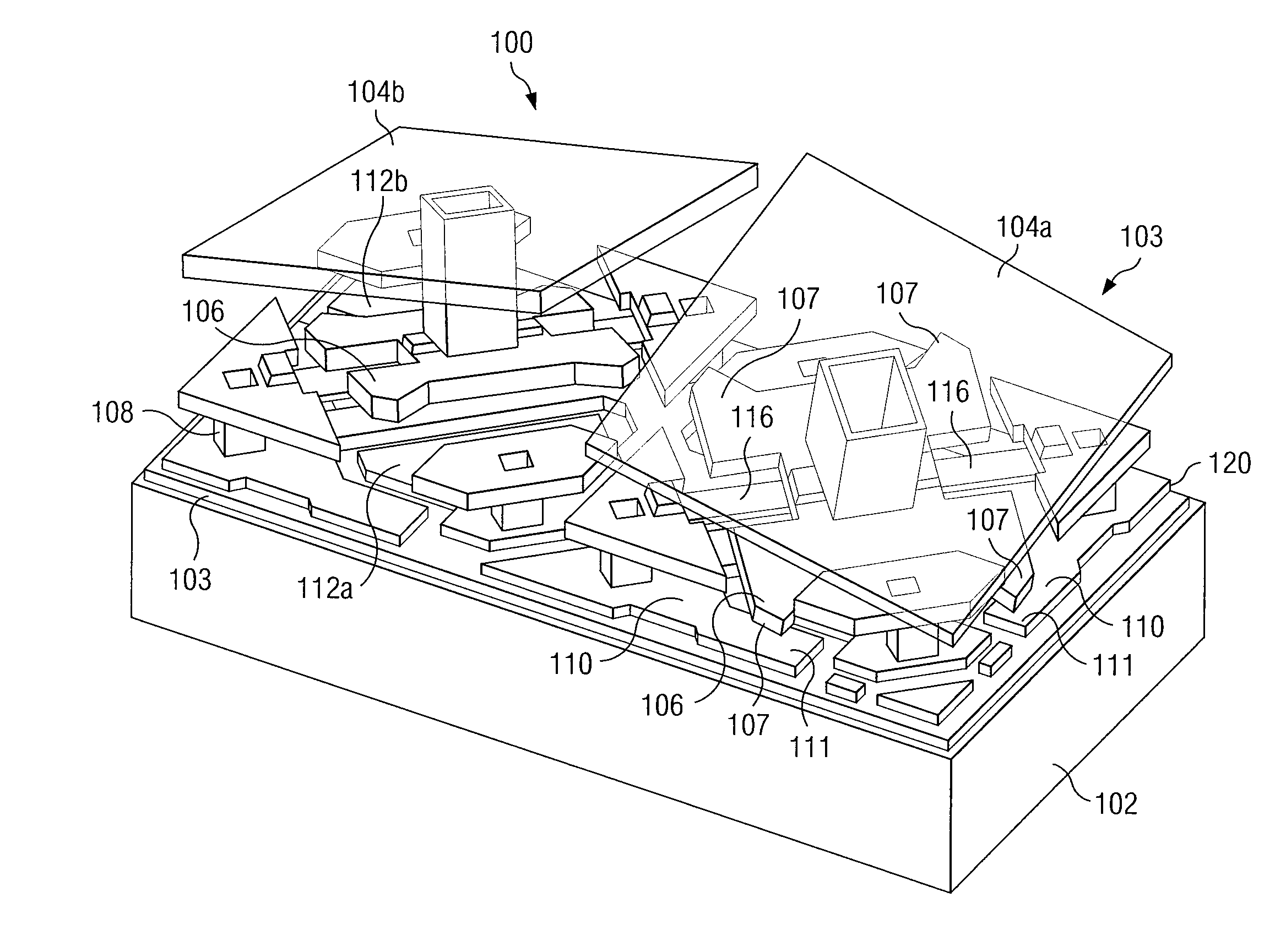
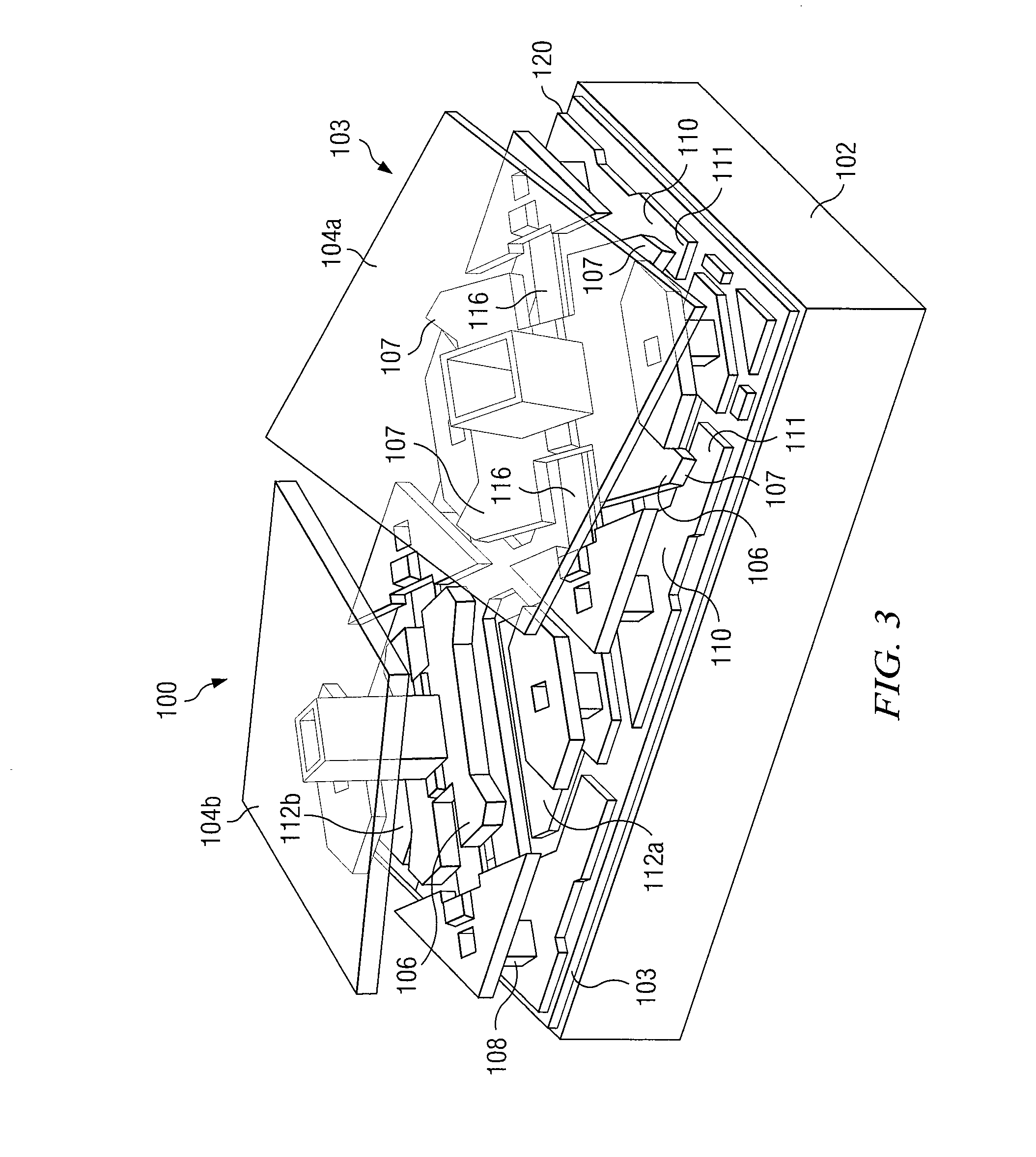
[0014]FIG. 1 illustrates an example of one embodiment of a projection system 10 that may be used to project an image 14 onto a projection surface 16. In the illustrated example, system 10 includes one or more light sources 20, a Digital Micromirror Device (DMD) system 24, and a controller 28 coupled as shown. In an example of operation, a light source 20 generates light, which is modulated by DMD system 24 to yield image 14. Controller 28 controls the operation of light source 20 and DMD system 24 by instructing (or “directing”) light source 20 and DMD system 24.

[0015]In particular embodiments, controller instructs DMD system 24 to have an active region and an amplitude modulation region. The active region may modulate light to generate...


PUM


Abstract

According to particular embodiments, a system comprises one or mores light sources, a Digital Micromirror Device (DMD) system, and a controller. A light source is configured to generate light, and the DMD system comprises DMD regions configured to modulate the light. The controller is configured to repeat the following for a number of iterations: instruct each light source to scroll the light across the DMD system at a current amplitude level; instruct one or more DMD regions to operate as one or more active regions that modulate a first portion of the light to generate an image; and instruct the remaining DMD regions to operate as an amplitude modulation region that receives a second portion of the light, the second portion of the light transitioning from a previous amplitude level to the current amplitude level.

Description

RELATED APPLICATION[0001]This application claims benefit under 35 U.S.C. §119(e) of U.S. Provisional Application Ser. No. 60 / 953,409, entitled “Techniques and Implementations for Laser Based Display Imaging Systems,” Attorney's Docket TI-64992, filed Aug. 1, 2007, by Philip S. King et al.TECHNICAL FIELD[0002]This invention relates generally to the field of image display systems and more specifically to a system and method for controlling a Digital Micromirror Device (DMD) system to generate an image.BACKGROUND[0003]Spatial light modulators may be used in image display systems. In some applications, spatial light modulators may generate an image by controlling individual elements to manipulate light in order to form an image. One example of a spatial light modulator is a Digital Micromirror Device (DMD) made by TEXAS INSTRUMENTS INCORPORATED. A DMD chip typically includes an array of micromirrors that move to manipulate light.SUMMARY OF THE DISCLOSURE[0004]In accordance with the pres...

Claims


Application Information

Patent Timeline
IPC IPC(8): G02B26/02
CPCG02B26/0833
Inventor KING, PHILIP SCOTT
Owner TEXAS INSTR INC
Why Eureka
Try Eureka