
Hydraulic circuit for construction machine

a technology for construction machines and hydraulic circuits, applied in fluid couplings, servomotors, couplings, etc., can solve the problems of poor operability, energy loss, and exert detrimental effects on the characteristics of other plot circuits, so as to prevent a surge in pressure, deterioration of operability, and energy loss

Inactive Publication Date: 2009-12-22
KOBELCO CONSTR MASCH CO LTD
View PDF15 Cites 11 Cited by
  • Summary
  • Abstract
  • Description
  • Claims
  • Application Information

AI Technical Summary

Benefits of technology

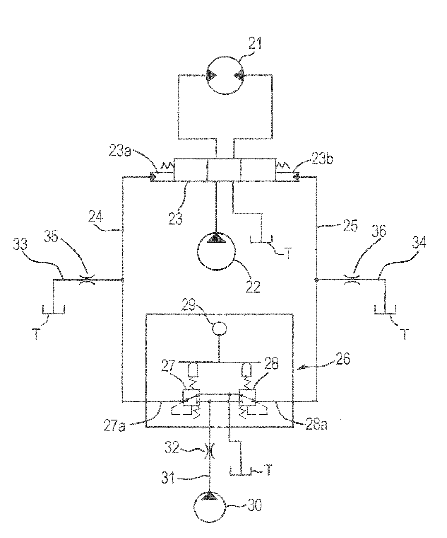
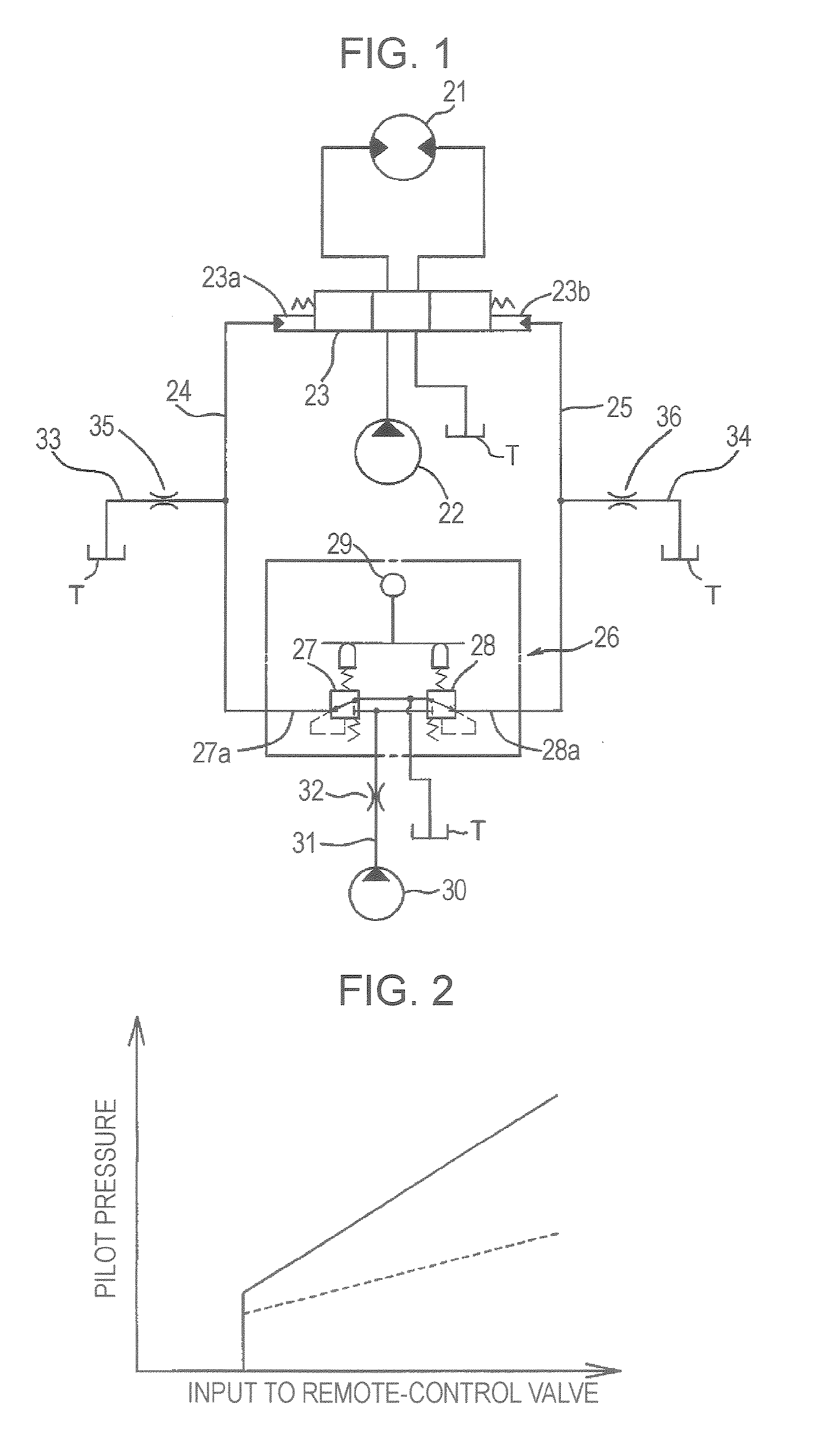
The present invention provides a hydraulic circuit for a construction machine that can prevent detrimental effects such as poor operability and energy loss while ensuring shock absorption during quick operation. The circuit includes a pilot hydraulic source, pressure-reducing valves, throttles, and a bleed-off line. The first throttle reduces the upstream pressure, while the second throttle modifies the rise in pilot pressure. This combination prevents a surge in pressure and shock caused by quick operation of the hydraulic actuator. The absolute value of the pilot pressure is regulated by the first throttle, and the rise in pilot pressure is moderated by the second throttle. This prevents deterioration of operability, energy losses, and harmful influences on other pilot circuits.

Problems solved by technology

Therefore, lever operation / valve stroke characteristics set for the remote-control valve 6 and the control valve 3 are warped, and the hydraulic actuator 1 cannot be operated accurately as an operator desires, resulting in poor operability.
However, this leads an increase in an upstream pressure (a primary pressure; discharge pressure of the pilot pump 10), and thus leads to an energy loss.
Moreover, this exerts detrimental effects on characteristics of other plot circuits since the pilot pump 10 is usually shared with the other pilot circuits.
Thus the above-described proposed solution creates new problems to be solved and is not expedient.

Method used


Image

  • Hydraulic circuit for construction machine
  • Hydraulic circuit for construction machine
  • Hydraulic circuit for construction machine

Examples


first embodiment (see figs.1 to 3)

First Embodiment (see FIGS. 1 to 3)

[0037]In FIG. 1, reference numbers 21, 22, and 23 denote a hydraulic actuator (a hydraulic motor as an example thereof) a hydraulic pump serving as a hydraulic source, and a control valve of the hydraulic pilot type that controls the operation of the hydraulic actuator 21, respectively. Pilot lines 24 and 25 are connected to pilot ports 23a and 23b, respectively, at either end of the control valve 23 for guiding pilot pressures.

[0038]A remote-control valve 26 operates the control valve 23, and downstream-pressure lines 27a and 28a of a pair of pressure-reducing valves 27 and 28, respectively, of the remote-control valve 26 are connected to the pilot lines 24 and 25, respectively. The downstream pressures of the pressure-reducing valves 27 and 28 according to operation amounts to a lever 20 serving as operating means are supplied to the control valve 23 via the pilot lines 24 and 25, respectively, as pilot pressures. Reference number 30 denotes a pi...

second embodiment (see figs.4 to 6)

Second Embodiment (see FIGS. 4 to 6)

[0048]Only aspects different from the first embodiment will be described in the following embodiments.

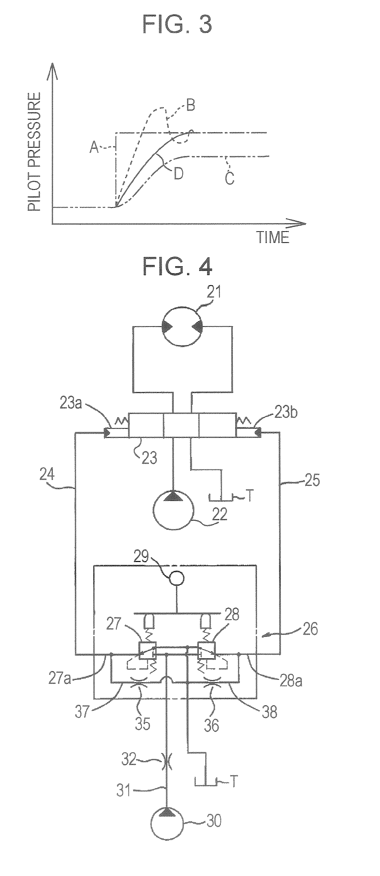
[0049]In a second embodiment, as shown in FIG. 4, internal paths 37 and 38 serving as bleed-off lines that connect the downstream-pressure lines 27a and 28a at downstream sides of the pressure-reducing valves 27 and 28, respectively, of the remote-control valve 26 with a tank line extending to a tank T are provided for the pressure-reducing valves 27 and 28, respectively. The second throttles 35 and 36 are disposed on the internal paths 37 and 38, respectively.

[0050]With this structures an excellent operability can also be ensured while surges in pressure in the pilot lines 24 and 25 are prevented by means of the first throttle 32 and the second throttles 35 and 36 in basically the same manner as in the first embodiment.

[0051]As described above, the bleed-off lines having the second throttles can be connected to the pilot lines 24 and 25 as extern...

third embodiment (see fig.7)

Third Embodiment (see FIG. 7)

[0056]In a third embodiment, a bleed-off line 41 having a second throttle 40 is disposed between the pilot lines 24 and 25 so as to connect the pilot lines 24 and 25. This bleed-off line 41 is connected to a tank T via the pilot line and the pressure-reducing valve that are not operated during the operation of the remote-control valve 26.

[0057]For example, when the pressure-reducing valve 27 at the left side in FIG. 7 is operated, the bleed-off line 41 is connected to the tank T via the pilot line 25 and the pressure-reducing valve 28 disposed at the right side in the drawing (inoperative side).

[0058]With this, one bleed-off line 41 and one second throttle 40 are sufficient for the operation. This leads to a simplified circuit structure, easy circuit assembly, and a reduction in costs.


PUM


Abstract

A hydraulic circuit including a first throttle disposed upstream of pressure-reducing valves of a remote-control valve, which operates a control valve of hydraulic pilot type, so as to reduce primary pressures supplied from a pilot pump to the pressure-reducing valves. Bleed-off lines connect pilot lines to tanks. Second throttles are disposed on the bleed-off lines, respectively, so as to moderate rises in the pilot pressures supplied to pilot ports of the control valve. The hydraulic circuit prevents detrimental effects such as deterioration of operability while ensuring shock absorption during quick operation.

Description

TECHNICAL FIELD[0001]The present invention relates to hydraulic circuits for construction machines such as hydraulic shovels whose hydraulic actuators are operated by control valves using remote-control valves.BACKGROUND ART[0002]When remote-control valves in construction machines of this type are quickly operated, pilot pressures output from pressure-reducing valves of the remote-control valves suddenly changes and a surge in pressure occurs in pilot lines. This causes quick operation or control valves and generates shock.[0003]To solve this problem, a technology described in Patent Document 1 is well known.[0004]This will be illustrated in FIG. 18 that is newly drawn for comparison.[0005]Reference numbers 1, 2, and 3 denote a hydraulic actuator (a hydraulic motor as an example thereof), a hydraulic pump serving as a hydraulic sources and a control valve of the hydraulic pilot type that controls the operation of the hydraulic actuator 1 respectively. Pilot lines 4 and 5 are connect...

Claims


Application Information

Patent Timeline
Patent Type & Authority Patents(United States)
IPC IPC(8): F15B11/08F16D31/02
CPCE02F9/128E02F9/2207E02F9/226E02F9/2267F15B13/0422E02F9/2285F15B2211/7058F15B2211/329F15B2211/355Y10T137/7758
Inventor ASAKAGE, TOMOHIKOTOJI, YUTAKATACHINO, MASAAKIFUJII, KAZUHIKO
Owner KOBELCO CONSTR MASCH CO LTD
Learn More