Stationary Induction Electric Device

a technology of induction electric device and induction coil, which is applied in the direction of inductance with magnetic core, basic electric elements, electrical apparatus, etc., can solve the problems of increased loss, prone to buckling of large wound iron cores, and change of magnetic body characteristics, so as to achieve suppressed loss

Active Publication Date: 2019-04-25
HITACHI LTD
View PDF0 Cites 2 Cited by
  • Summary
  • Abstract
  • Description
  • Claims
  • Application Information

AI Technical Summary

Benefits of technology

The stationary induction electric device can reduce loss.

Problems solved by technology

However, among the wound iron cores using amorphous magnetic ribbons, especially large-sized wound iron cores are prone to buckling due to their own weights and easily deform.
When the iron core deforms, there arises a problem that characteristics of the magnetic body are changed and the loss is increased.

Method used


Image

  • Stationary Induction Electric Device
  • Stationary Induction Electric Device
  • Stationary Induction Electric Device

Examples


first embodiment

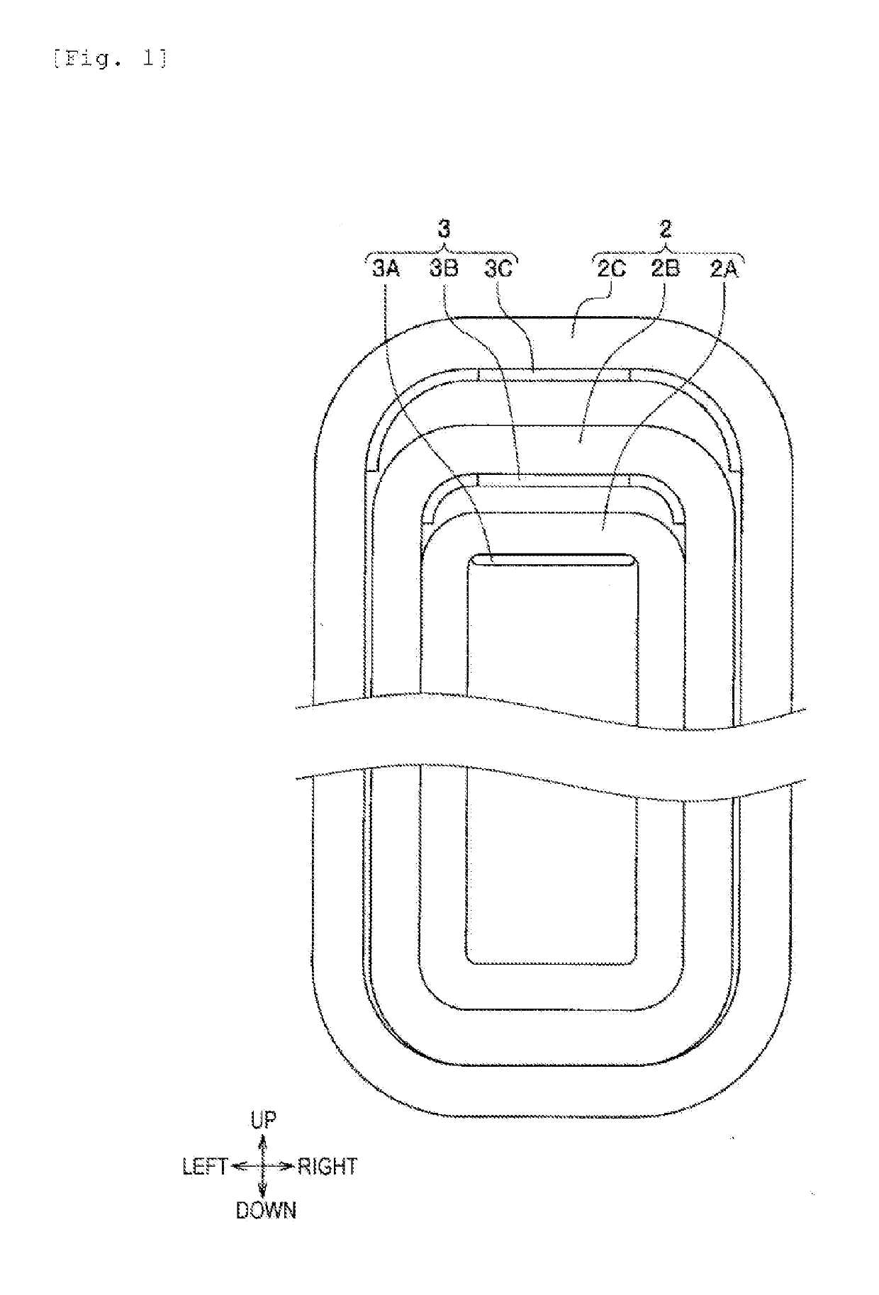
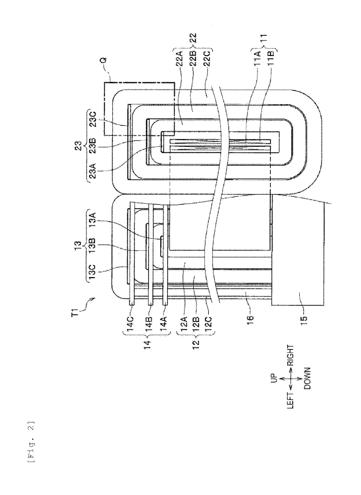
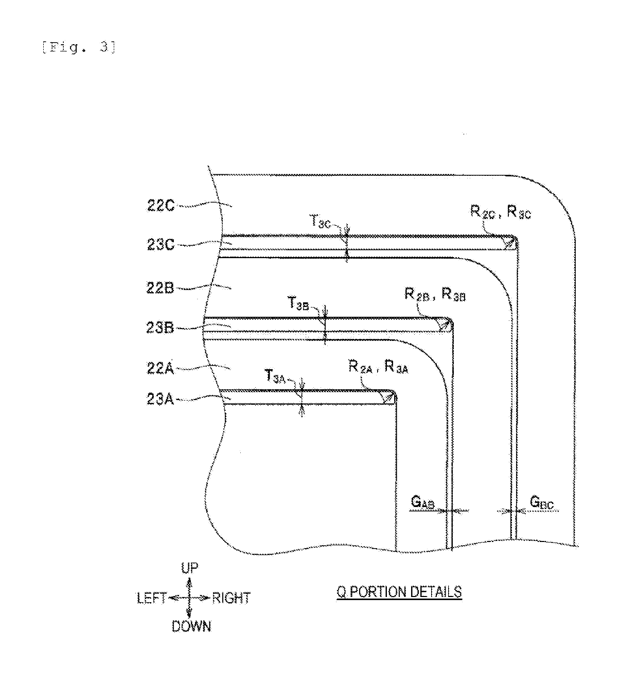
[0024]Next, the configuration of a stationary induction electric device T1 according to a first embodiment of the invention will be described with reference to FIG. 2 to FIG. 4. Here, FIG. 2 is a partially cutaway front view of the stationary induction electric device T1, and FIG. 3 is an enlarged view of a main portion Q thereof. Further, FIG. 4 is a front view of an iron core 22.

[0025]In FIG. 2, the stationary induction electric device T1 is a transformer with a single phase tripod structure, and includes two iron cores 12 and 22 which are arranged adjacently, and a winding 11 wound around the iron cores 12 and 22. Here, the winding 11 includes a primary winding 11A wound in inner side and a secondary winding 11B wound in outer side. A lower portion fixing member 15 is fixed to the installation place of the stationary induction electric device T1.

[0026]Although only one support post 16 is shown in FIG. 2, the support post 16 is arranged at four corners of the lower portion fixing ...

second embodiment

[0041]Next, a stationary induction electric device T2 according to a second embodiment of the invention will be described.

[0042]FIG. 5 is a partially cutaway front view of the stationary induction electric device T2. In FIG. 5, parts corresponding to those in FIGS. 1 to 4 are given the same reference signs and numerals, and the description thereof may be omitted in some cases.

[0043]In FIG. 5, the stationary induction electric device T2 is a transformer with a single phase tripod structure, and includes iron cores 12 and 22, a winding 11, support plate portions 33 and 43, an upper portion fixing member 14, a lower portion fixing member 15, a plurality of support posts 16, and support beam portions 17 and 27.

[0044]Here, the configurations of the iron cores 12 and 22, the winding 11, the upper portion fixing member 14, the lower portion fixing member 15, and the support posts 16 are the same as those of the first embodiment (see FIG. 2). Like the support plate portions 13 and 23 of the...

third embodiment

[0047]Next, a stationary induction electric device T3 according to a third embodiment will be described.

[0048]FIG. 6 is a partially cutaway front view of the stationary induction electric device T3. In FIG. 6, parts corresponding to those in FIGS. 1 to 5 are given the same reference signs and numerals, and the description thereof may be omitted in some cases.

[0049]In FIG. 6, the stationary induction electric device T3 is a transformer with a single phase tripod structure, and includes iron cores 12 and 22, a winding 11, support plate portions 33 and 32, an upper portion fixing member 14, a lower portion fixing member 15, a plurality of support posts 16, and support beam portions 18 and 28.

[0050]Here, the configurations of the iron cores 12 and 22, the winding 11, the upper portion fixing member 14, the lower portion fixing member 15, the support posts 16 are the same as those of the first embodiment (see FIG. 2). In addition, among the support plate portions 33 and 43, the configura...


PUM

PropertyMeasurementUnit
curvature radiusaaaaaaaaaa
thicknessaaaaaaaaaa
widthaaaaaaaaaa

Abstract

The invention is directed to a stationary induction electric device that can reduce loss. To this end, the stationary induction electric device is provided with a first iron core block erected and formed in an annular shape, a second iron core block configured to surround the outer periphery of the first iron core block, a winding wound around the first and the second iron core blocks, a first support plate supporting the upper portion of the first iron core block from below, and a second support plate supporting the upper portion of the second iron core block from below, and a curvature radius of a curved portion appearing on the outer periphery of the lower portion of the second iron core block is made larger than a curvature radius of a curved portion appearing on the outer periphery of the upper portion of the second iron core block.

Description

TECHNICAL FIELD[0001]The present invention relates to a stationary induction electric device.BACKGROUND ART[0002]A stationary induction electric device such as a transformer and a reactor has an iron core composed with a magnetic body. A wound iron core using an amorphous magnetic ribbon has an advantage that it has lower loss than an iron core in which electromagnetic steel sheets are laminated. However, among the wound iron cores using amorphous magnetic ribbons, especially large-sized wound iron cores are prone to buckling due to their own weights and easily deform. When the iron core deforms, there arises a problem that characteristics of the magnetic body are changed and the loss is increased. For this reason, support members are frequently used in this kind of stationary induction electric device to suppress the deformation of the iron core. For example, the following Patent Literature 1 describes that “ . . . the iron core support member 100 is formed by integrating a side su...

Claims


Application Information

Patent Timeline
Patent Type & Authority Applications(United States)
IPC IPC(8): H01F27/25H01F27/06
CPCH01F27/25H01F27/06H01F27/263H01F27/266H01F30/10H01F41/0226H01F17/06H01F27/24
Inventor MIYAMOTO, NAOYAYAMADA, YUISHIGAMI, TAKASHIKURITA, NAOYUKINISHIMIZU, AKIRA
Owner HITACHI LTD
Why Eureka
Try Eureka