Switching power supply unit

a technology of switching power supply and power supply unit, which is applied in the direction of electric variable regulation, process and machine control, instruments, etc., can solve the problems of unable to achieve substantial improvement of efficiency, and reducing efficiency in a waiting sta

Inactive Publication Date: 2003-03-11
MURATA MFG CO LTD
View PDF16 Cites 19 Cited by
  • Summary
  • Abstract
  • Description
  • Claims
  • Application Information

AI Technical Summary

Benefits of technology

According to the present invention, without using control ICs and complicated circuits for separate excitation oscillation, the oscillation frequency automatically decreases by making use of cross regulation of a transformer itself in a waiting state, and accordingly loss can be suppressed and by that much, the efficiency can be increased. Furthermore, dissipation power can be easily decreased in a waiting state by providing the secondary winding of a transformer with a switch.

Problems solved by technology

However, in a switching power supply unit in which self-oscillation takes place, such as an RCC, there is a problem of decreasing efficiency because the oscillation frequency increases in a waiting state, and also in a switching power supply unit of a general PWM type having separate excitation oscillation, there is a problem of the decreasing efficiency in a waiting state as in the above RCC because the oscillation frequency is constant regardless of load size.
Accordingly the dissipation power of an IC and circuit for controlling the main switching element cannot be neglected, and particularly the dissipation power in a waiting state becomes large and not negligible and a substantial improvement of efficiency cannot be expected with these designs.

Method used


Image

  • Switching power supply unit
  • Switching power supply unit
  • Switching power supply unit

Examples


first embodiment

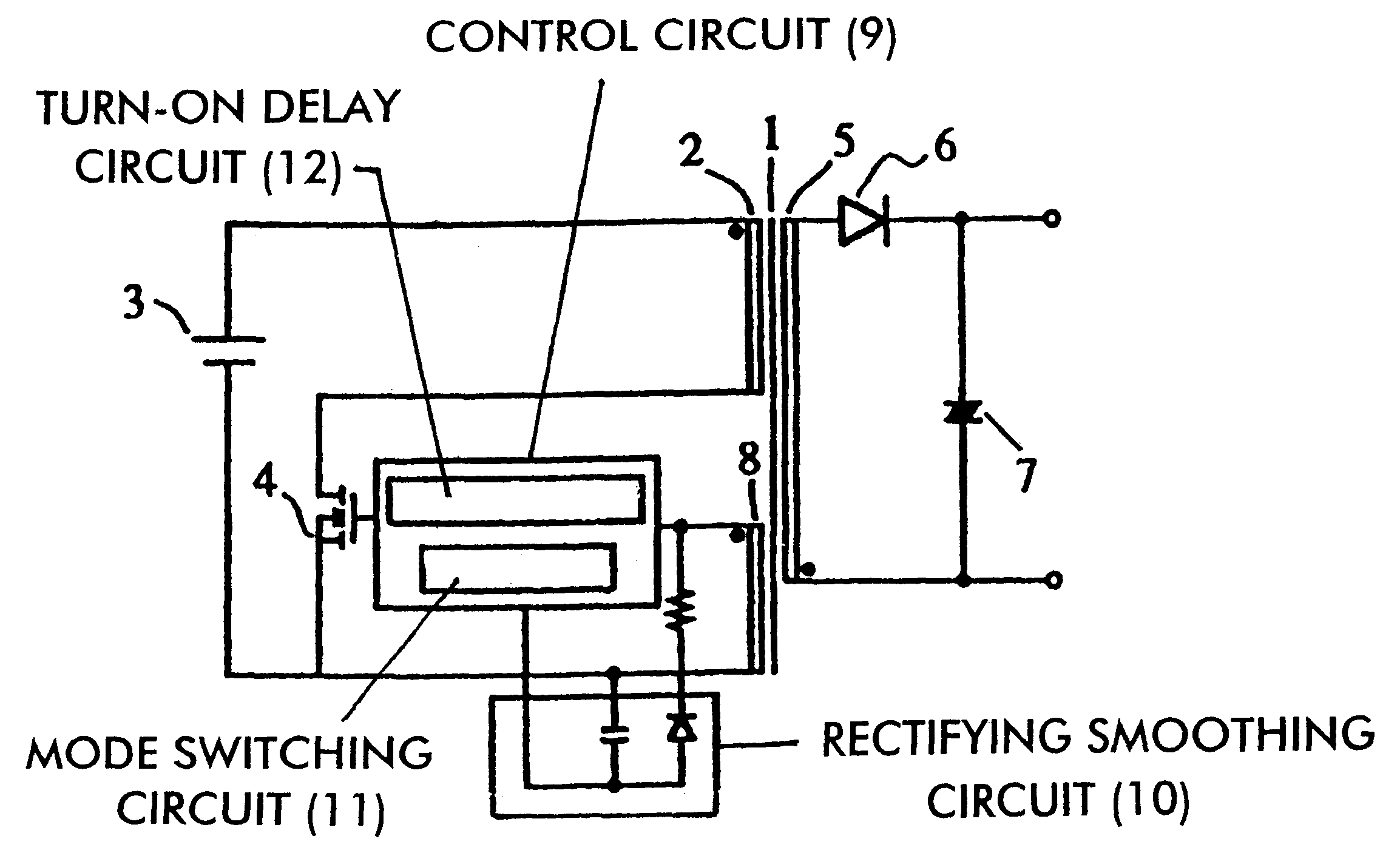
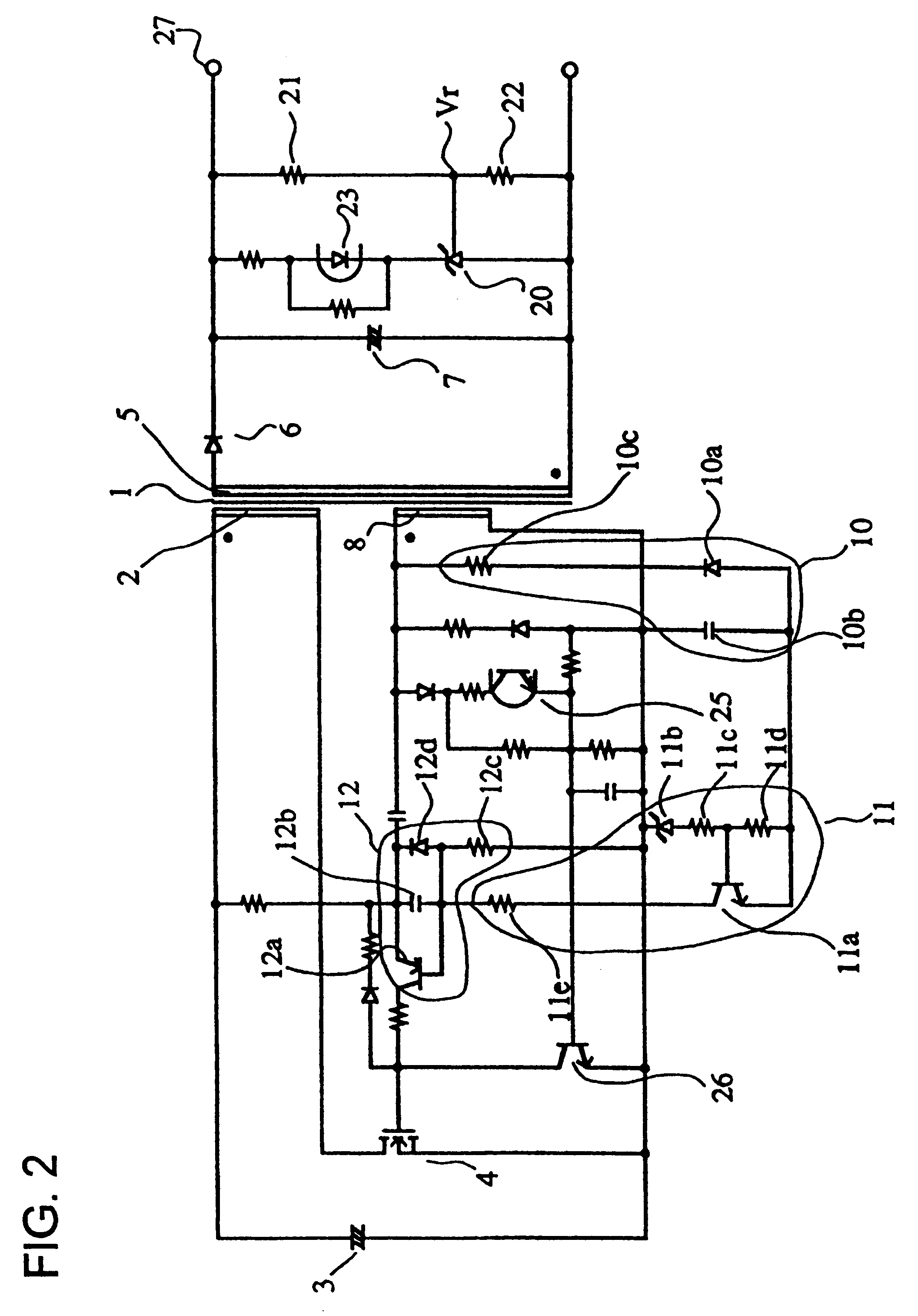
FIG. 2 shows a circuit diagram of a RCC type switching power supply unit of the present invention. Moreover, regarding the reference numerals, the same portions as shown in FIG. 1 are given the same reference numerals.

An output voltage detecting circuit including a shunted regulator 20 and voltage divider resistors 21 and 22 is connected to a secondary winding 5 of a transformer 1, and a photodiode 23 is connected in series to the shunted regulator 20. The shunted regulator 20 controls the current between the cathode and the anode so that the voltage of a reference voltage input terminal Vr is kept constant. The change of the current is converted into the intensity of light from the photodiode 23, and the light is input into a phototransistor 25 connected to a bias winding 8 on the side of a primary winding of the transformer 1. A transistor 26 is connected to the emitter of the phototransistor 25, and the collector of the transistor 26 is connected to the gate of a MOSFET 4. In thi...

second embodiment

FIG. 6 shows the present invention. In the RCC type switching power supply unit of this embodiment, a second winding output voltage is made available by increasing the number of windings of the secondary winding 5 of the transformer 1. This voltage is rectified by a diode 31 and is output as a second output voltage from a terminal 32. A switch 30 is connected between a terminal 27 and the terminal 32, and both terminals can be connected or disconnected by turning the switch 30 on or off. When the switch 30 is turned off, a high voltage at the terminal 27 is output to the output terminal 32. Here, the output voltage from the output terminal 27 is stabilized by a voltage stabilizer. Therefore, when the switch 30 is turned on, the output voltage from the output terminal 32 becomes the output voltage from the output terminal 27. As a result, in accordance with the turn ratio of the transformer 1, the output voltage of the bias winding 8 decreases. When the output voltage from the bias w...


PUM


Abstract

A switching power supply unit comprises: a transformer, a main switching element, a rectifying smoothing circuit, a mode switching circuit and a delay circuit. The transformer has a primary winding, a secondary winding and a bias winding. The main switching element is connected to the primary winding and receives an output of the bias winding as a positive feedback so as to form a ringing choke converter operating in self-excitation oscillation. The rectifying smoothing circuit is connected to the bias winding. The mode switching circuit is turned on and off depending on whether or not the rectifying smoothing voltage of the rectifying smoothing circuit is a threshold voltage or higher. The delay circuit is coupled to the mode switching circuit and is connected between the main switching element and the bias winding and delays the output of the bias winding and applies the delayed output to the main switching element. The delay circuit lengthens a turn-on delay time when the mode switching circuit detects an output voltage of the rectifying smoothing circuit which is less than the threshold voltage.

Description

1. Field of the InventionThe present invention relates to a switching power supply unit made up of a ringing choke converter in which a main switching element such as an oscillation transistor, etc., is connected to a primary winding of a transformer and a self-excitation oscillation takes place by positive feedback of the output from a bias winding of the transformer to the main switching element.2. Description of the Related ArtIn a ringing choke converter (hereinafter referred to as an RCC) in which a main switching element such as an oscillation transistor, etc., is connected to a primary winding of a transformer and an output is supplied to the secondary winding by self-oscillation, the oscillation frequency increases in a waiting state because of the following reason.Because an RCC operates so that either a primary winding current or a secondary winding current may always flow, when the primary current and the secondary current are combined, the current seems to continuously f...

Claims


Application Information

Patent Timeline
Patent Type & Authority Patents(United States)
IPC IPC(8): H02M3/24H02M3/338H02M3/28H02J1/00
CPCH02M3/3385Y02B70/16H02M2001/0032Y02B70/10H02M1/0032
Inventor NISHIDA, AKIOTAKEMURA, HIROSHI
Owner MURATA MFG CO LTD
Why Eureka
Try Eureka