Stationary induction electric device
a technology of induction electric device and induction coil, which is applied in the direction of transformer/inductance details, inductance with magnetic core, electrical apparatus, etc., can solve the problems of large-sized wound iron core prone to buckling, increased loss, and change of magnetic body characteristics, so as to achieve suppressed loss
- Summary
- Abstract
- Description
- Claims
- Application Information
AI Technical Summary
Benefits of technology
Problems solved by technology
Method used
Image
Examples
first embodiment
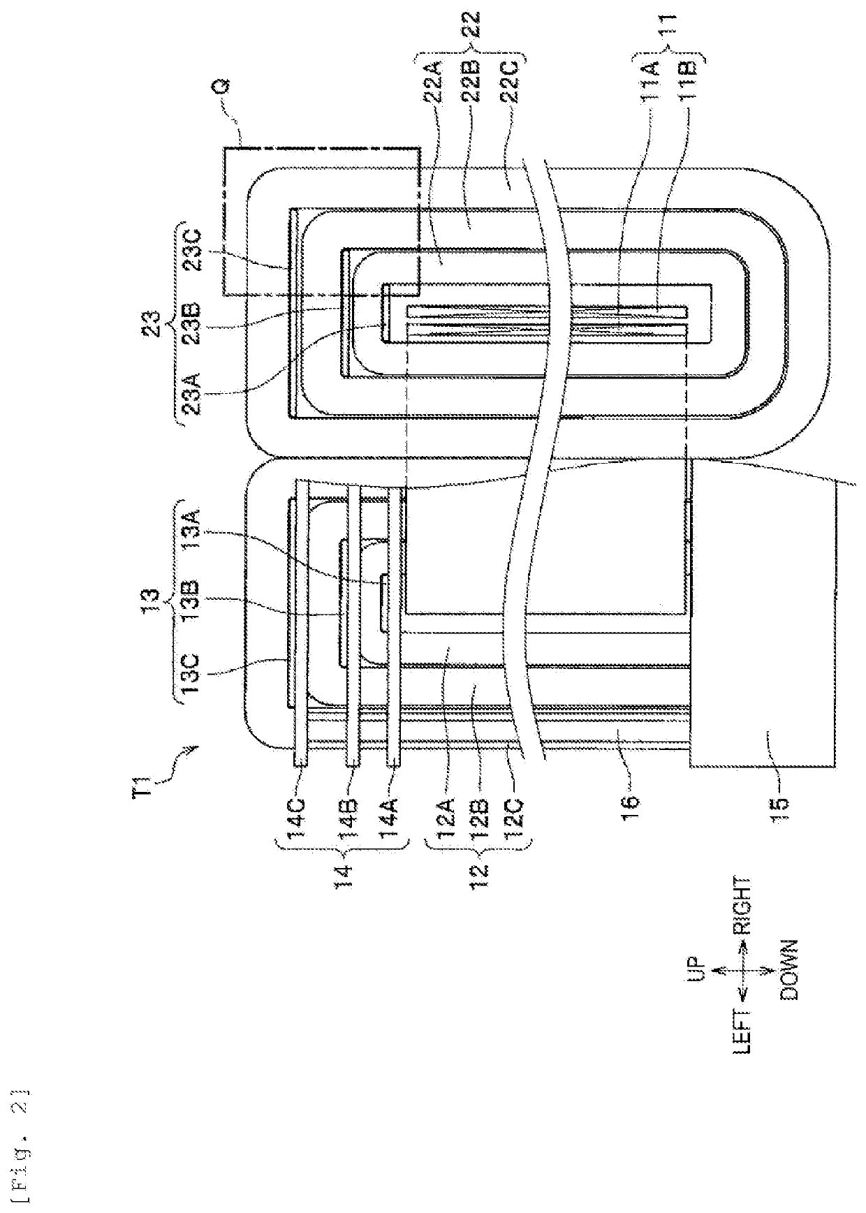
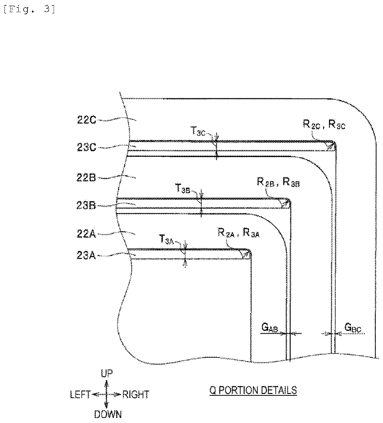
[0024]Next, the configuration of a stationary induction electric device T1 according to a first embodiment of the invention will be described with reference to FIG. 2 to FIG. 4. Here, FIG. 2 is a partially cutaway front view of the stationary induction electric device T1, and FIG. 3 is an enlarged view of a main portion Q thereof. Further, FIG. 4 is a front view of an iron core 22.
[0025]In FIG. 2, the stationary induction electric device T1 is a transformer with a single phase tripod structure, and includes two iron cores 12 and 22 which are arranged adjacently, and a winding 11 wound around the iron cores 12 and 22. Here, the winding 11 includes a primary winding 11A wound in inner side and a secondary winding 11B wound in outer side. A lower portion fixing member 15 is fixed to the installation place of the stationary induction electric device T1.
[0026]Although only one support post 16 is shown in FIG. 2, the support post 16 is arranged at four corners of the lower portion fixing ...
second embodiment
[0041]Next, a stationary induction electric device T2 according to a second embodiment of the invention will be described.
[0042]FIG. 5 is a partially cutaway front view of the stationary induction electric device T2. In FIG. 5, parts corresponding to those in FIGS. 1 to 4 are given the same reference signs and numerals, and the description thereof may be omitted in some cases.
[0043]In FIG. 5, the stationary induction electric device T2 is a transformer with a single phase tripod structure, and includes iron cores 12 and 22, a winding 11, support plate portions 33 and 43, an upper portion fixing member 14, a lower portion fixing member 15, a plurality of support posts 16, and support beam portions 17 and 27.
[0044]Here, the configurations of the iron cores 12 and 22, the winding 11, the upper portion fixing member 14, the lower portion fixing member 15, and the support posts 16 are the same as those of the first embodiment (see FIG. 2). Like the support plate portions 13 and 23 of the...
third embodiment
[0047]Next, a stationary induction electric device T3 according to a third embodiment will be described.
[0048]FIG. 6 is a partially cutaway front view of the stationary induction electric device T3. In FIG. 6, parts corresponding to those in FIGS. 1 to 5 are given the same reference signs and numerals, and the description thereof may be omitted in some cases.
[0049]In FIG. 6, the stationary induction electric device T3 is a transformer with a single phase tripod structure, and includes iron cores 12 and 22, a winding 11, support plate portions 33 and 32, an upper portion fixing member 14, a lower portion fixing member 15, a plurality of support posts 16, and support beam portions 18 and 28.
[0050]Here, the configurations of the iron cores 12 and 22, the winding 11, the upper portion fixing member 14, the lower portion fixing member 15, the support posts 16 are the same as those of the first embodiment (see FIG. 2). In addition, among the support plate portions 33 and 43, the configura...
PUM
| Property | Measurement | Unit |
|---|---|---|
| curvature radius | aaaaa | aaaaa |
| thickness | aaaaa | aaaaa |
| width | aaaaa | aaaaa |
Abstract
Description
Claims
Application Information
 - R&D
- Intellectual Property
- Life Sciences
- Materials
- Tech Scout
- Unparalleled Data Quality
- Higher Quality Content
- 60% Fewer Hallucinations
Browse by: Latest US Patents, China's latest patents, Technical Efficacy Thesaurus, Application Domain, Technology Topic, Popular Technical Reports.
© 2025 PatSnap. All rights reserved.Legal|Privacy policy|Modern Slavery Act Transparency Statement|Sitemap|About US| Contact US: help@patsnap.com


