Spinal cord stimulation guidance system and method of use

a spinal cord stimulation and guidance system technology, applied in the field of neurostimulation systems, can solve the problems of difficult ascertaining the anatomy of the spinal cord, difficult to use, and difficult to use the mri compatible scs system availabl

Active Publication Date: 2019-05-16
PACESETTER INC
View PDF8 Cites 6 Cited by
  • Summary
  • Abstract
  • Description
  • Claims
  • Application Information

AI Technical Summary

Benefits of technology

This patent describes a method and system for modeling and treating spinal cord stimulation (SCS) using a lead positioned near the spinal cord. The method involves acquiring impedance and evoked compound action potential (ECAP) signals from the lead, and creating a patient-specific anatomical model based on these signals. The anatomical model is then used to transform a dorsal column map template to create a three-dimensional model with material properties assigned to each element. The system can also detect neural tissue damage based on the impedance and ECAP signals, and adjust therapy parameters to change the stimulation waveform or lead position. The technical effects of this patent include improved precision and accuracy in SCS treatment, as well as improved safety and efficiency in detecting and addressing neural tissue damage.

Problems solved by technology

The process requires multiple software packages and specialized personnel to perform the tasks, which make conventional modeling approach difficult in the clinical setting.
However, some of the SCS systems available are not MRI-compatible, requiring MRI images to be taken prior to implant of the SCS system, and other modalities (e.g., X-rays, computed tomography (CT) scan) are needed to determine SCS lead position after implant.
Moreover, detailed SC anatomy is difficult to ascertain with clinical MRI sequences, with dermatomal fiber tracts from such MRI images being difficult to visualize.
Further, solving the computational model with the conventional approach is time-consuming, making this difficult to use in the clinical setting during an office visit or SCS implant.

Method used


Image

  • Spinal cord stimulation guidance system and method of use
  • Spinal cord stimulation guidance system and method of use
  • Spinal cord stimulation guidance system and method of use

Examples


Embodiment Construction

[0040]While multiple embodiments are described, still other embodiments of the described subject matter will become apparent to those skilled in the art from the following detailed description and drawings, which show and describe illustrative embodiments of disclosed inventive subject matter. As will be realized, the inventive subject matter is capable of modifications in various aspects, all without departing from the spirit and scope of the described subject matter. Accordingly, the drawings and detailed description are to be regarded as illustrative in nature and not restrictive.

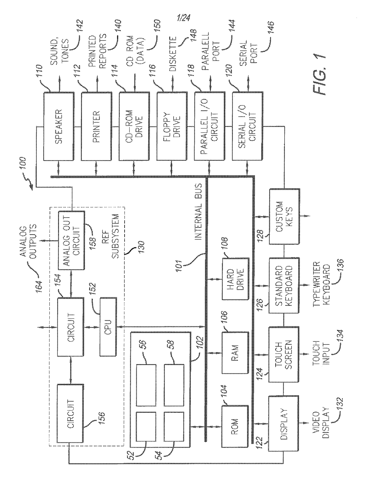
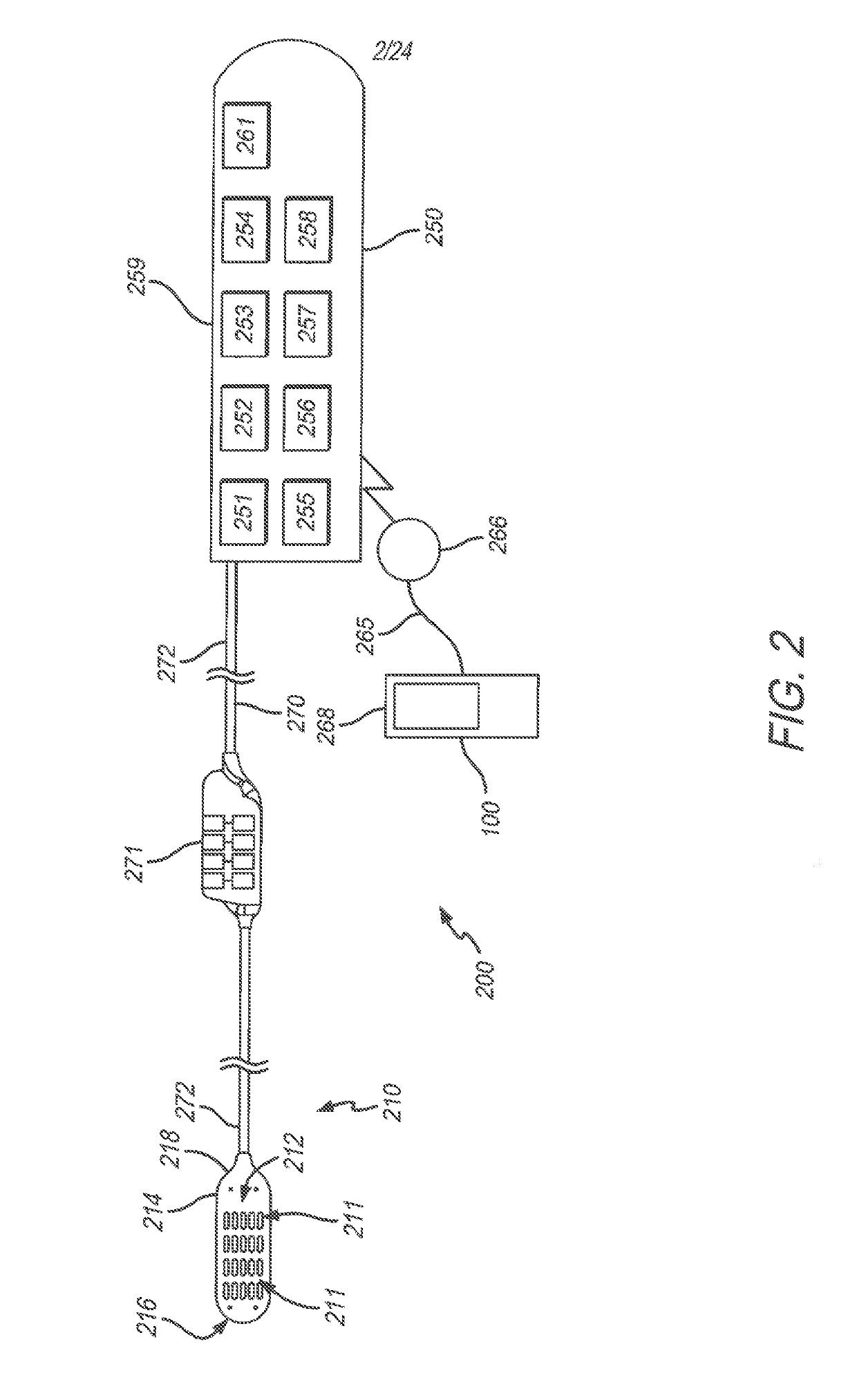
[0041]Embodiments described herein include a patient-specific spinal cord stimulation (SCS) programming guidance system 100 that may be used during SCS implantation, during office visits, and the like. The system 100 may be used by a clinician and / or patient to determine and / or select optimal SCS settings (e.g., amplitude, duration, frequency, type of stimulation pulses, selection of electrode configurat...


PUM


Abstract

A system and method for modeling patient-specific spinal cord stimulation (SCS) is disclosed. The system and method acquire impedance and evoked compound action potential (ECAP) signals from a lead positioned proximate to a spinal cord (SC). The lead includes at least one electrode. The system and method determine a patient-specific anatomical model based on the impedance and ECAP signals, and transform a dorsal column (DC) map template based on a DC boundary of the patient-specific anatomical model. Further, the system and method map the transformed DC map template to the patient-specific anatomical model. The system and method may also include the algorithms to solve extracellular and intracellular domain electrical fields and propagation along neurons. The system and method may also include the user interfaces to collect patient responses and compare with the patient-specific anatomical model as well as using the patient-specific anatomical model for guiding SCS programming.

Description

RELATED APPLICATION DATA[0001]This application is a divisional of U.S. patent application Ser. No. 14 / 958,725, filed Dec. 3, 2015, which claims priority from U.S. provisional application Ser. No. 62 / 088,451 filed Dec. 5, 2014, entitled “SPINAL CORD STIMULATION GUIDANCE SYSTEM AND METHOD OF USE,” both of which are hereby expressly incorporated by reference in its entirety.BACKGROUND OF THE INVENTION[0002]Embodiments of the present disclosure generally relate to neurostimulation (NS) systems, and more particularly to model-based programming guidance for implantation of spinal cord stimulation (SCS) systems.[0003]NS systems are devices that generate electrical pulses and deliver the pulses to nervous tissue to treat a variety of disorders. For example, SCS has been used to treat chronic and intractable pain. Another example is deep brain stimulation, which has been used to treat movement disorders such as Parkinson's disease and affective disorders such as depression. While a precise u...

Claims


Application Information

Patent Timeline
Patent Type & Authority Applications(United States)
IPC IPC(8): A61B5/00A61N1/372A61N1/05A61N1/378A61N1/36A61B5/04A61B5/053
CPCA61B5/407A61N1/37247A61N1/0553A61N1/3787A61N1/36A61B5/04001A61B5/0536A61B5/6823A61B5/4887A61B5/0537A61B2562/0209A61B2562/046G16H30/40G16H40/63G16H20/40G16H50/50G16H20/30A61B5/24A61B5/388
Inventor MIN, XIAOYIKENT, ALEXANDER
Owner PACESETTER INC
Why Eureka
Try Eureka