
Power supply apparatus and image forming apparatus having adjusted load power

a technology of power supply apparatus and image forming apparatus, which is applied in the direction of power conversion systems, electrographic process apparatus, instruments, etc., can solve the problems of increasing the size and cost of the image forming apparatus, and achieve the effect of preventing an increase in the size of the apparatus

Active Publication Date: 2019-05-30
CANON KK
View PDF0 Cites 4 Cited by
  • Summary
  • Abstract
  • Description
  • Claims
  • Application Information

AI Technical Summary

Benefits of technology

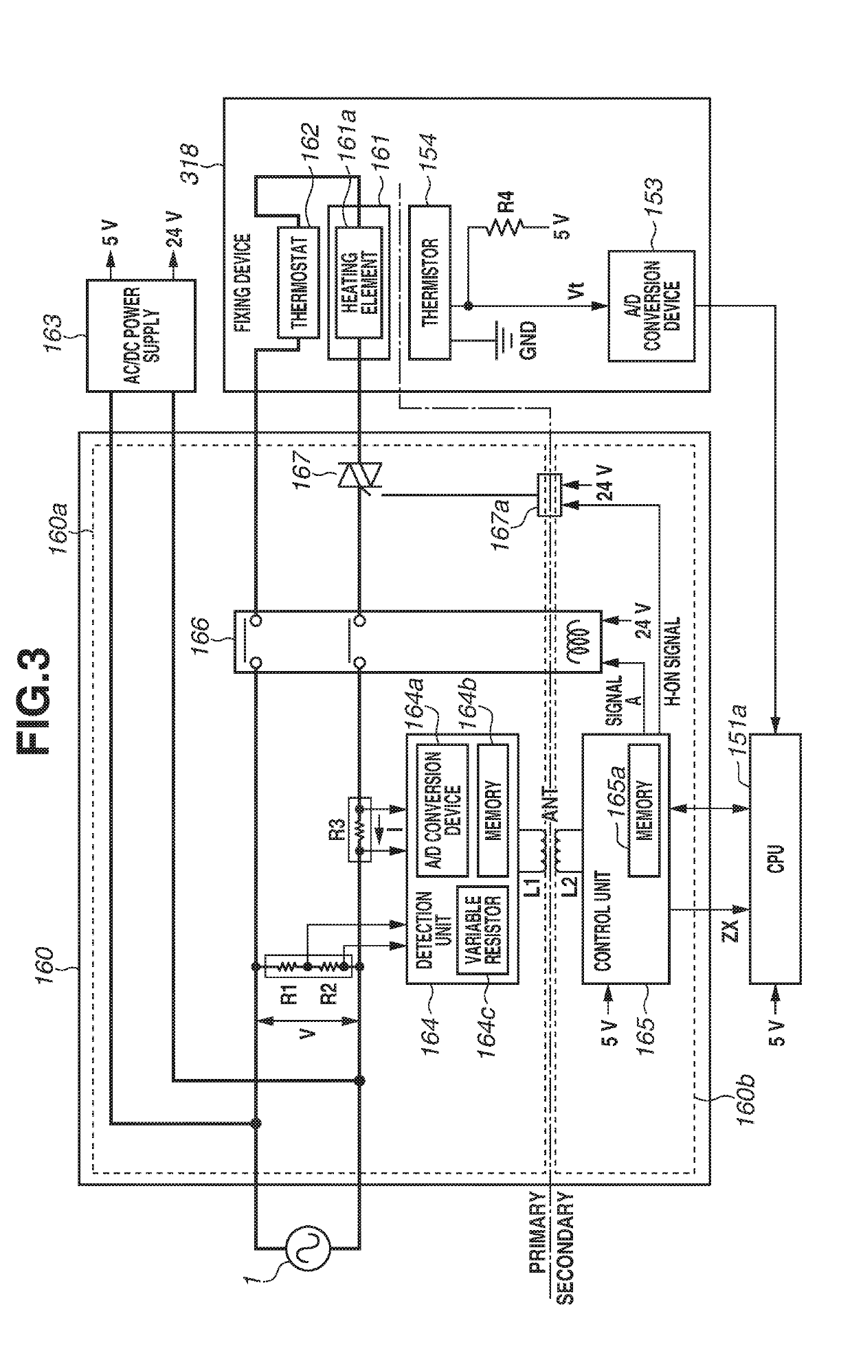
The patent is about a way to prevent a device from getting bigger while keeping two sections of the device insulated from each other. The device includes a circuit that adjusts power from a power supply to a load. Another circuit controls this adjustment. The device also has a detector that measures a parameter related to power supply. A communication unit in each circuit allows for wireless communication between them. The first communication unit gets power from a signal generated by the controller in the second circuit and uses this power to transmit information about the detection result to the second circuit. The controller then controls the adjustment unit based on this information. The technical effect of this invention is that it allows for efficient adjustment of power supply without increasing the size of the device.

Problems solved by technology

Specifically, use of a transformer in the technique discussed in United States Patent Publication Application No. 2014 / 0093268 leads to an increase in size of the image forming apparatus and costs.

Method used


Image

  • Power supply apparatus and image forming apparatus having adjusted load power
  • Power supply apparatus and image forming apparatus having adjusted load power
  • Power supply apparatus and image forming apparatus having adjusted load power

Examples


Embodiment Construction

[0018]Various exemplary embodiments of the disclosure will be described below with reference to the drawings. It should be noted that the shapes, relative positions, etc. of components described in the exemplary embodiments are to be changed as needed depending on the configuration of an apparatus to which the disclosure is applied and various conditions, and the exemplary embodiments described below are not intended to limit the scope of the disclosure.

[0019]A first exemplary embodiment will be described below.

[Image Forming Apparatus]

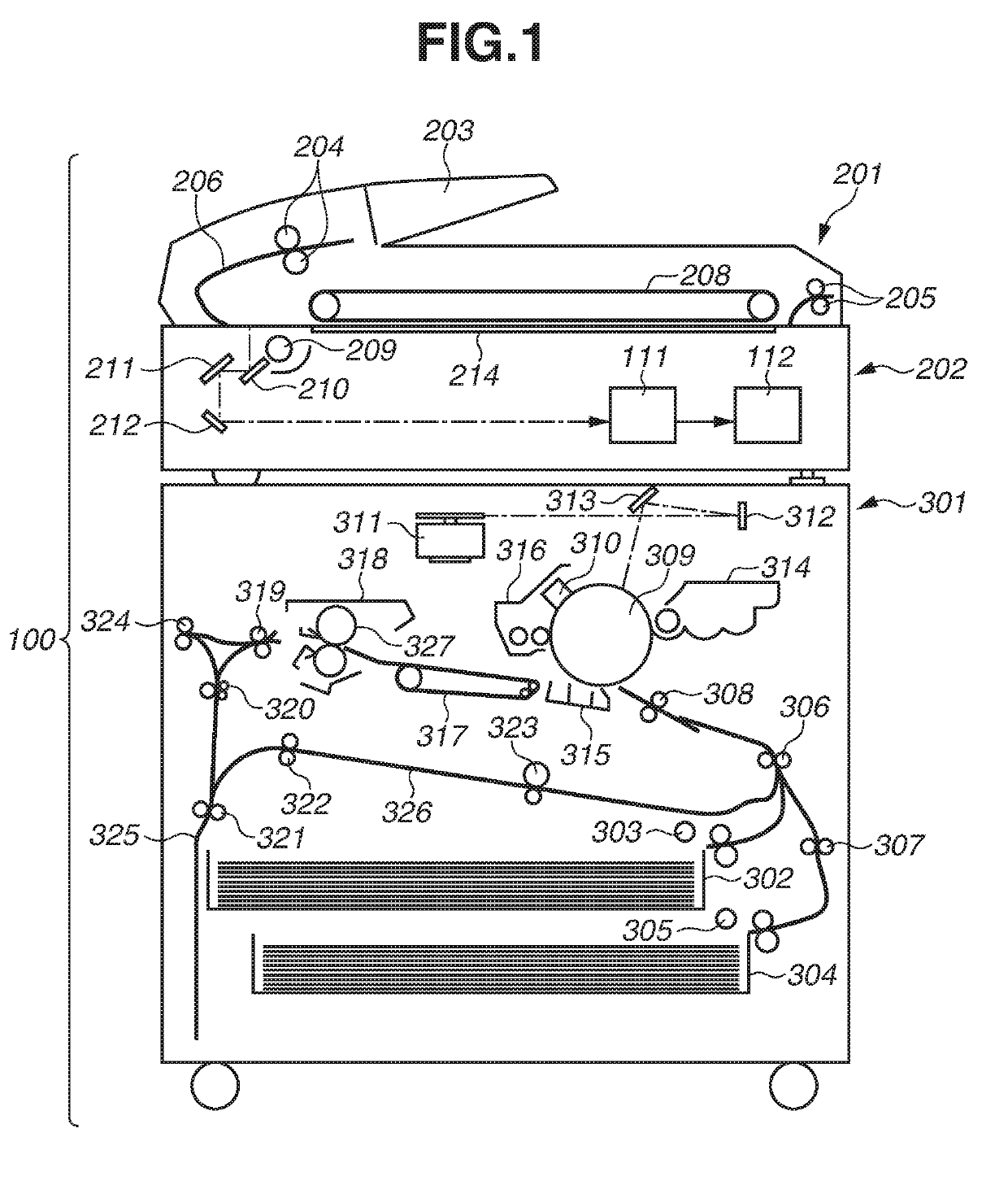
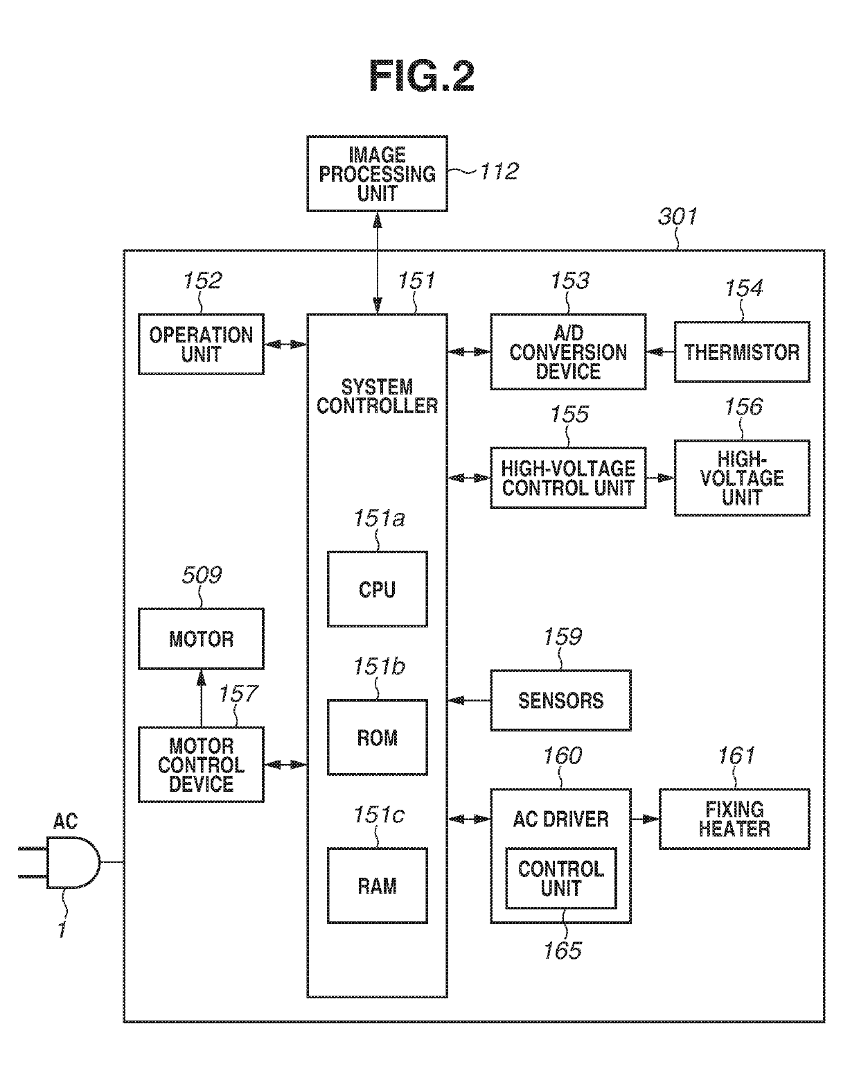
[0020]FIG. 1 is a cross sectional view illustrating the configuration of a monochrome electrophotographic copying machine (hereinafter, “image forming apparatus”) 100 with a sheet conveyance device which is used in the present exemplary embodiment. The image forming apparatus 100 is not limited to the copying machine and can be, for example, a facsimile apparatus, a printing machine, or a printer. The recording method is not limited to the electrophot...


PUM


Abstract

A power supply apparatus including a first circuit and a second circuit insulated from the first circuit includes an adjustment unit and a detector in the first circuit, a controller in the second circuit, and first and second communication units in the first and second circuits, respectively. The adjustment unit is configured to adjust power. The controller is configured to control the adjustment unit. The detector is configured to detect a parameter. The second communication unit is configured to perform wireless communication with the first communication unit. The first communication unit is operated with power supplied to the first communication unit by a signal generated in the first communication unit due to a signal output from the controller to the second communication unit, and transmits information about a result of detection by the detector to the second communication unit. The controller controls the adjustment unit based on the information.

Description

BACKGROUND OF THE INVENTIONField of the Invention[0001]One disclosed aspect of the embodiments relates to a power supply apparatus and an image forming apparatus that control the power supplied to a load.Description of the Related Art[0002]Conventionally, an apparatus operated with power supplied from a commercial power supply is known in which the voltage of the commercial power supply that is input to a primary side and the current flowing in the primary side are detected on a secondary side insulated from the primary side.[0003]United States Patent Publication Application No. 2014 / 0093268 discusses an image forming apparatus in which a voltage applied to a fixing heater provided on a primary side is detected on a secondary side via a transformer. A central processing unit (CPU) controls the temperature of the fixing heater based on the detection result.[0004]In the technique discussed in United States Patent Publication Application No. 2014 / 0093268, the transformer has both the f...

Claims


Application Information

Patent Timeline
Patent Type & Authority Applications(United States)
IPC IPC(8): G03G15/00H04N1/00
CPCG03G15/80H04N1/00888H04N1/00978H04N1/00082H04N1/00076H02M5/22H02M5/293
Inventor ISHIKAWA, JUNJI
Owner CANON KK
Learn More