Sheet feeding apparatus and image forming apparatus

a technology of feeding apparatus and forming apparatus, which is applied in the direction of thin material processing, instruments, article separation, etc., can solve the problems of poor operability, difficult to reduce the size of the cam, so as to prevent an increase in the entire size of the apparatus

Inactive Publication Date: 2012-09-20
CANON KK
View PDF9 Cites 9 Cited by
  • Summary
  • Abstract
  • Description
  • Claims
  • Application Information

AI Technical Summary

Benefits of technology

[0012]In view of the present circumstances described above, it is an object of the present invention to provide a sheet feeding apparatus and an image forming apparatus capable of preventing an increase in the entire size of the apparatus even in a case of using a link member.

Problems solved by technology

The sheet feeding apparatus of such a configuration requires one vertical reciprocating motion of the sheet supporting member for each rotation of a drive shaft, which imposes a problem in that it is difficult to reduce the size (outermost diameter) of the cam.
Then, the user has to frequently replenish sheets, thereby causing a problem of poor operability.
Since there is a trade-off between the size of the cam and the rotational angle of the sheet supporting member, it is difficult to reduce the size of the cam.
Such conventional sheet feeding apparatuses can reduce the size of the cam, but has a problem in that it is difficult to reduce the entire size of the sheet feeding apparatus under the constraints of fulcrum placement of a lever member abutting against the cam and serving as a link member so as to transmit a force to the sheet supporting member.
Thus, the above arrangement can reduce the outermost diameter of the cam, but may increase the entire size of the sheet feeding apparatus.
This arrangement imposes constraints on the place where the turning fulcrum of the lever member can be positioned between the rotational trajectory of the cam and the rotational trajectory of the sheet supporting member.
Further, the turning fulcrum of the lever member is projected toward a downstream side surface of the feed roller, whereby this arrangement can reduce the outermost diameter of the cam, but may increase the entire size of the sheet feeding apparatus.
An increase in the entire size of sheet feeding apparatus increases the entire size of the image forming apparatus housing the sheet feeding apparatus, whereby this arrangement imposes a problem of enlarging the installation place of the image forming apparatus.

Method used


Image

  • Sheet feeding apparatus and image forming apparatus
  • Sheet feeding apparatus and image forming apparatus
  • Sheet feeding apparatus and image forming apparatus

Examples


first embodiment

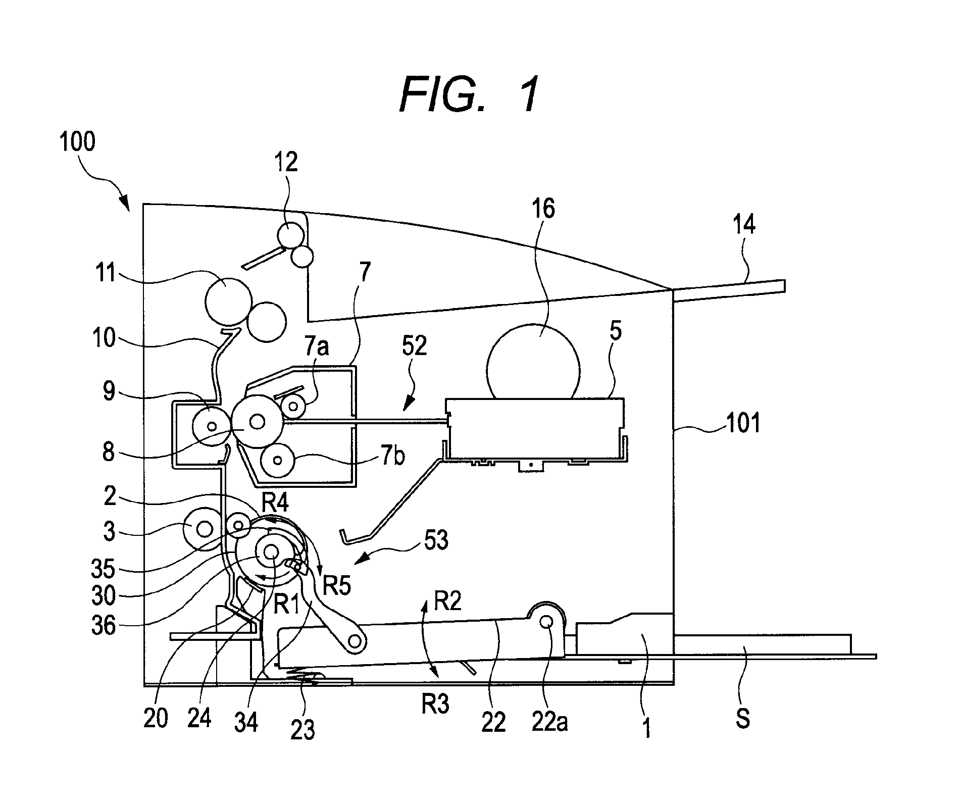
[0050]FIG. 1 illustrates a schematic configuration of a printer 100 as an example of an image forming apparatus having a sheet feeding apparatus according to the present invention. In FIG. 1, an image forming portion 52 is disposed in a printer body 101 as an image forming apparatus body and performs image formation by an electrophotographic system. A sheet feeding apparatus 53 feeds a sheet S to the image forming portion 52.

[0051]The image forming portion 52 includes a laser exposure apparatus 5, a photosensitive drum 8 for forming a toner image, a transfer roller 9 for transferring the toner image formed on the photosensitive drum 8 to a sheet S, and the like. A process cartridge 7 includes the photosensitive drum 8, a charge roller 7a, a developing unit 7b, and the like and is attachable to and detachable from a printer body 101.

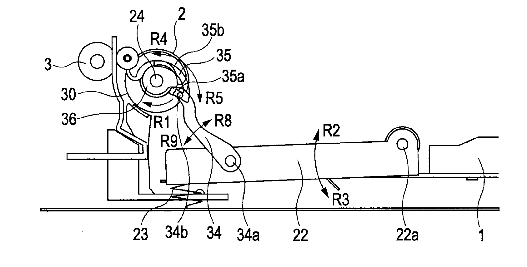
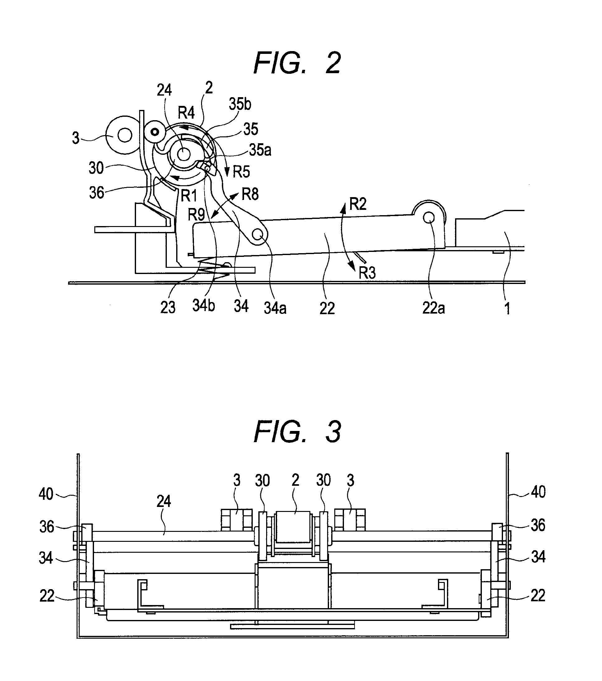
[0052]The sheet feeding apparatus 53 includes a feed roller 2, a sheet tray 1 as a sheet storage portion, and a lifting plate 22 liftably disposed in the...

second embodiment

[0079]Next, the present invention will be described. FIGS. 10A and 10B describe a configuration of the sheet feeding apparatus of the present embodiment. Note that the same reference numerals or characters in FIG. 2 refer to the same or identical components in FIGS. 10A and 10B.

[0080]In FIGS. 10A and 10B, a protruding portion 36a is disposed on a cam surface of a feed cam 36. As illustrated in FIG. 11, the protruding portion 36a is protrudingly provided at a height H on the cam surface of the feed cam 36. FIG. 11 illustrates a gap G between the link guide hole 35 and the engaging boss 34b. According to the present embodiment, the height H of the protruding portion 36a and the gap G between the link guide hole 35 and the engaging boss 34b have a relation of H

[0081]As illustrated in FIG. 10A and 10B, a link spring 39 is interposed as a link member biasing member between the link member 34 and the lifting plate 22. The link spring 39 is a torsion coil spring, one end of which is loc...

third embodiment

[0100]Next, the present invention will be described. FIG. 14 describes a configuration of a sheet feeding apparatus according to the present embodiment. Note that the same reference numerals or characters in FIG. 2 refer to the same or identical components in FIG. 14.

[0101]In FIG. 14, the link member 70 is rotatably supported by the lifting plate 22 around the link member boss 70a. A guide member 71 as a rotation regulating portion is rotatably provided around the drive shaft 24 in a direction indicated by the arrow R1 and in the opposite direction thereof. A guide member hole 71a forming a long groove is provided in the guide member 71. The movement of the link member 70 is regulated by engaging the guide member hole 71a with a boss 70b provided in a rotation end of the link member 70. A guide member stopper 72 is provided in the frame to regulate the rotation angle of the guide member 71. The drive shaft 24, the feed cam 36, the link member 70, the guide member 71, and the guide m...


PUM


Abstract

A link member is rotatably supported by a lifting plate. When the lifting plate moves upward and downward, the movement of the link member is guided by a guide portion provided on a link guide hole. Before sheet feeding starts, the movement of the link member is regulated by a holding portion provided on a lower end of the guide portion so as to hold the lifting plate in a standby position against a biasing force of a feed spring. When the sheet is fed, a feed cam rotating integrally with a feed roller presses the link member to release the link member from being locked by the holding portion of the link guide hole to thereby make the link member movable along the guide portion.

Description

BACKGROUND OF THE INVENTION[0001]1. Field of the Invention[0002]The present invention relates to a sheet feeding apparatus and an image forming apparatus, and more particularly to an arrangement for lifting a sheet supporting member having sheets stacked thereon so as to press the sheets against a feed roller.[0003]2. Description of the Related Art[0004]Today, among image forming apparatuses such as a copy machine, a printer, a facsimile machine and the like, widely used types of image forming apparatus feed a sheet from a sheet feeding apparatus to an image forming portion to form an image. Here, the sheet feeding apparatus generally has a sheet cassette serving as a sheet storage portion and being attachable to and detachable from the body of the apparatus, and automatically feeds a sheet stored in the sheet cassette to the image forming portion.[0005]For example, there is known sheet cassette arranged to be able to lift and lower a sheet supporting member which has sheets stacked...

Claims


Application Information

Patent Timeline
Patent Type & Authority Applications(United States)
IPC IPC(8): B65H3/06B65H5/06B65H1/08
CPCB65H3/0607B65H2403/512B65H2403/531B65H2403/532B65H2801/06B65H2402/54G03G15/00G03G21/00
Inventor TAKIGUCHI, MASATOSHI
Owner CANON KK
Why Eureka
Try Eureka