Image forming apparatus

Active Publication Date: 2015-10-01
KONICA MINOLTA INC
View PDF1 Cites 3 Cited by
  • Summary
  • Abstract
  • Description
  • Claims
  • Application Information

AI Technical Summary

Benefits of technology

[0007]It is an object of the present invention to provide an image forming apparatus having a function to clean the exhaust air from the image forming apparatus and a function to cl

Problems solved by technology

In the conventional image forming apparatus, however, since one motor is used in common for the fan of the interi

Method used


Image

  • Image forming apparatus
  • Image forming apparatus
  • Image forming apparatus

Examples


Embodiment Construction

General Structure of Image Forming Apparatus; See FIGS. 1 and 2

[0024]In the following, an image forming apparatus 1 according to an embodiment is described with reference to the drawings. In the drawings, the same members and parts are provided with the same reference symbols, and the same descriptions are not repeated.

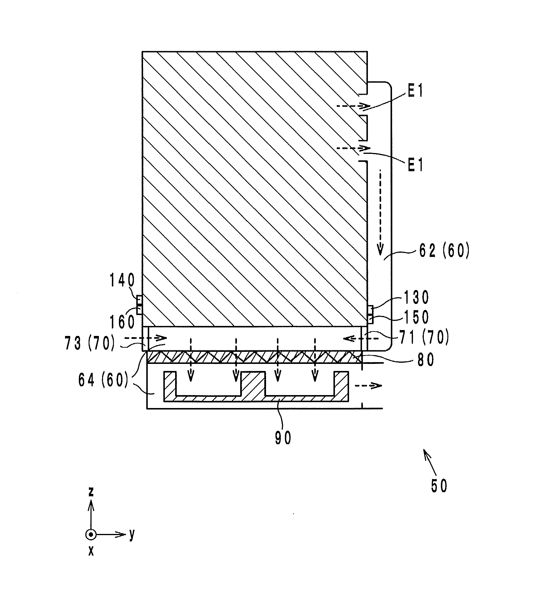
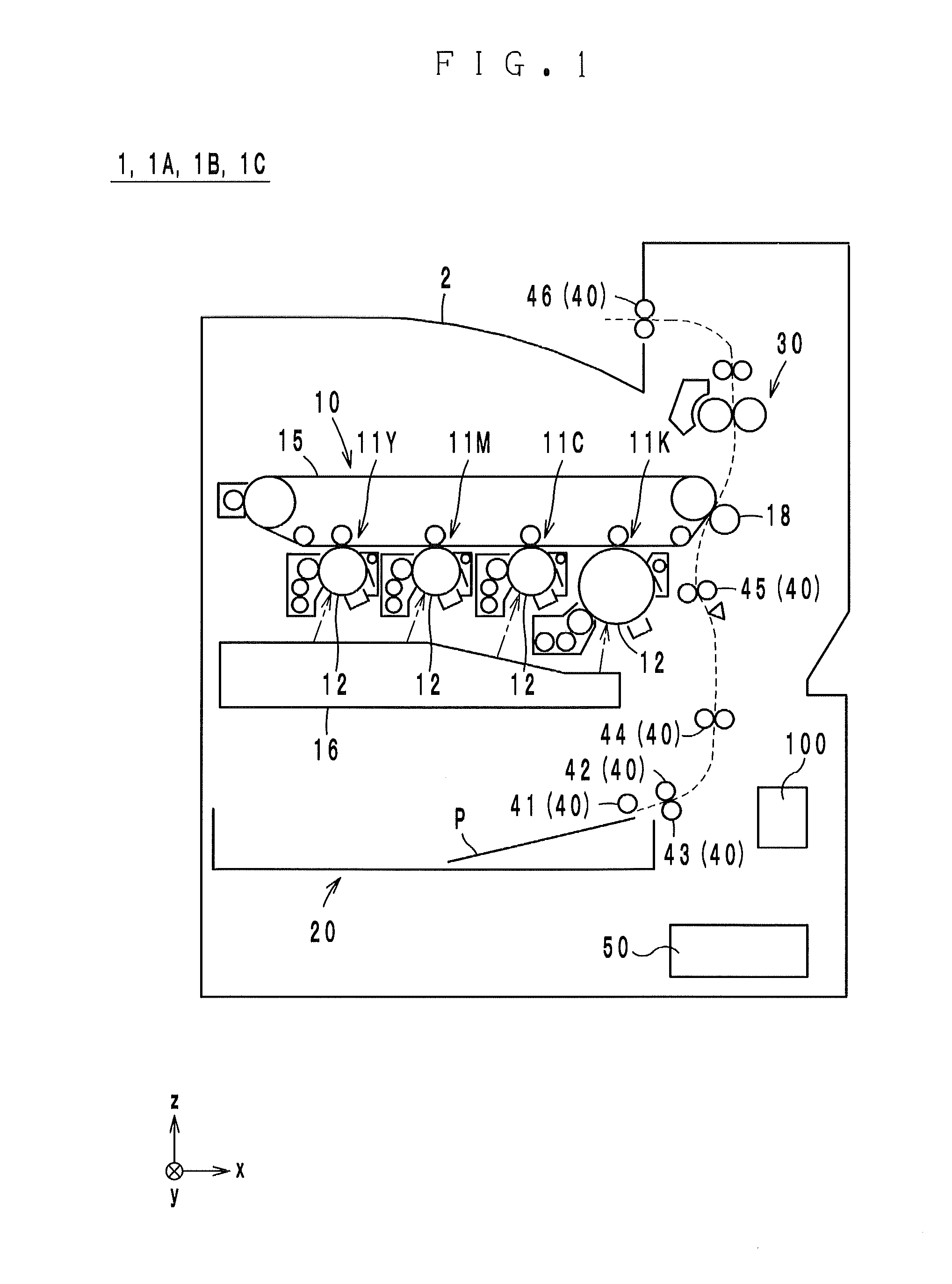
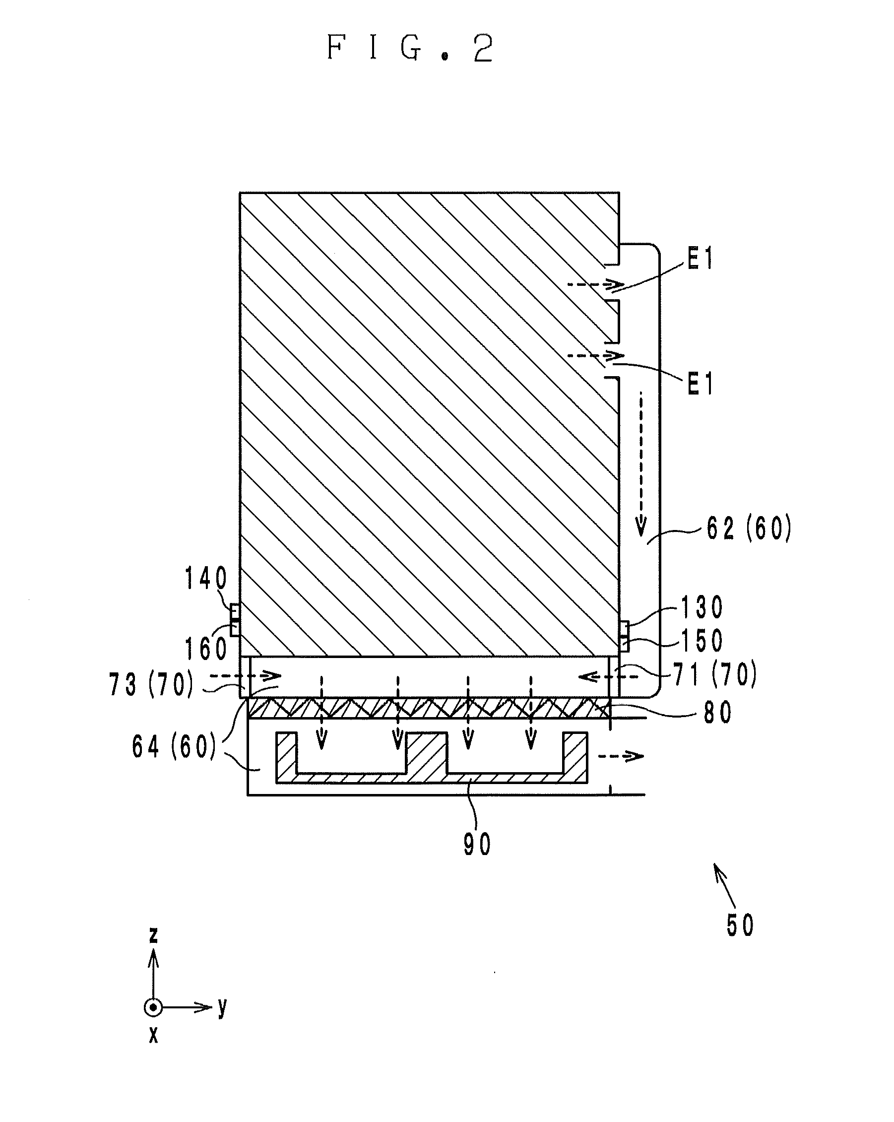
[0025]The image forming apparatus 1 is an electrophotographic color printer. As illustrated in FIG. 1, the image forming apparatus 1 comprises a control unit 100 configured to control the members and the parts of the image forming apparatus 1, an image forming section 10, a sheet feed cassette 20, a fixing device 30, a conveyance section 40, and an air cleaning system 50.

[0026]The image forming section 10 includes image forming units 11Y, 11M, 11C and 11K, an intermediate transfer belt 15, a second transfer roller 18, and an exposure unit 16. The image forming units 11Y, 11M, 11C and 11K are configured to form images in colors of Y (yellow), M (magenta), C (cyan) and ...


PUM


Abstract

An image forming apparatus has: an exhaust air duct capable of forming a first air flow path for an exhaust air cleaning function and a second air flow path for a room air cleaning function, the exhaust air duct having a common use space used in common for the exhaust air cleaning function and the room air cleaning function; a switching member configured to switch a flow path in the exhaust air duct, depending on which of the cleaning functions is activated; a fan configured to discharge air from the common use space in an active state of the exhaust air cleaning function and in an active state of the room air cleaning function; and a control unit configured to control the switching member and to adjust a rotation speed of the fan, depending on which of the cleaning functions is activated.

Description

[0001]This application claims benefit of priority to Japanese Patent Application No. 2014-059057 filed Mar. 20, 2014, the content of which is incorporated herein by reference.BACKGROUND OF THE INVENTION[0002]1. Field of the Invention[0003]The present invention relates to an image forming apparatus, and more particularly to an image forming apparatus having a function to clean the exhaust air therefrom and a function to clean the air in a room where the image forming apparatus is placed.[0004]2. Description of Related Art[0005]Electrophotographic image forming apparatuses typically generate dust (developers, paper powder, etc.), volatile organic compounds, odor and others while operating for image formation. Meanwhile, it has been demanded that image forming apparatuses carry out air cleaning in the offices where the image forming apparatuses are placed. In order to comply with the demand, Japanese Patent Laid-Open Publication No. 2011-75997 suggested an image forming apparatus compr...

Claims


Application Information

Patent Timeline
IPC IPC(8): G03G21/20
CPCG03G21/206G03G2215/0132
Inventor SATOU, MASAYUKITASHIRO, SHIGERUMATSUURA, KUNIYAYAMAGUCHI, MASAHIROMIZUNO, HIROSHIYOSHIKAWA, SHOICHI
Owner KONICA MINOLTA INC
Why Eureka
Try Eureka