Engine device

a technology of engine and supercharger, which is applied in the direction of electrical control, vessel auxillary drive, vessel construction, etc., can solve the problems of excessive increase of supercharger supercharger supercharger pressure, compressor pressure out of balance, surging (pulsation), etc., and achieve optimal air-to-fuel ratio, excellent responsiveness, optimal effect of air-to-fuel ratio

Inactive Publication Date: 2016-12-15
JAPAN SHIP MACHINERY & EQUIPMENT ASSOCIATION +1
View PDF13 Cites 0 Cited by
  • Summary
  • Abstract
  • Description
  • Claims
  • Application Information

AI Technical Summary

Benefits of technology

[0012]According to the embodiment of the present invention of the instant application, the engine device includes the intake manifold that supplies the air in the cylinder, the exhaust manifold that discharges the exhaust gas from the cylinder, the gas injector that mixes the air supplied from the intake manifold with the fuel gas, the supercharger that compresses the air by means of the exhaust gas from the exhaust manifold, and the intercooler that cools the compressed air compressed with the supercharger and supplies the compressed air to the intake manifold, and the main throttle valve is provided on the connection section between the air discharge port of the supercharger and the inlet of the intercooler, and the air supply bypass flow path configured to connect the air inflow port of the supercharger with the inlet of the intercooler is provided, and the bypass valve is arranged in the air supply bypass flow path, and when the load of the engine is lower than a predetermined threshold value, the opening degree of the main throttle valve is controlled, and the flow rate of the air is set in accordance with the load of the engine, whereas when the load of the engine is equal to or higher than a predetermined threshold value, the main throttle valve is set to a predetermined opening degree, and the opening degree of the bypass valve is controlled, and the flow rate of the air is set in accordance with the load of the engine, so that based on the structure in which the main throttle valve and the bypass valve are provided, the flow rate of air in the intake manifold can be controlled with high accuracy, and the flow rate of the air can be controlled with excellent responsiveness with respect to variation in load. The air supply bypass flow path functions as a buffer flow path with respect to the supercharger and the intake manifold, so that a response speed by which the flow rate of the air is optimally set in accordance with an increase or decrease in load can be increased by controlling the opening degree of the bypass valve. In particular, in the high load area on which variation in load exerts great influence, the bypass valve control with excellent responsiveness is executed, so that the severe deficiency of the flow rate of the air with respect to the variation on load is unlikely to occur, and an optimal air-to-fuel ratio can be set.
[0013]Also, the engine device further includes the pressure sensor configured to measure air pressure in the intake manifold, the load detection sensor configured to detect the load of the engine, the engine control portion configured to control the respective opening degrees of the main throttle valve and the bypass valve, and the engine control portion sets the opening degree of the main throttle valve or the bypass valve based on a difference between target air pressure based on the engine load detected by the load detection sensor and measurement pressure detected by the pressure sensor, so that the target pressure is set in accordance with the detected load, the valve opening degree is controlled based on the feedback control, which makes it possible to provide an appropriate flow rate of the air with respect to the actual load. Accordingly, the optimal air-to-fuel ratio can be set with excellent responsiveness with respect to the variation on load.
[0014]Also, according to the embodiment of the present invention, the flow rate of the air supplied to the intake manifold is set, and the flow rate of the air passing through the main throttle valve can be optimally controlled, so that the deficiency of the flow rate of the air supplied to the intake manifold can be prevented. Accordingly, the flow rate of the air can be controlled with excellent responsiveness with respect to a rapid increase in load, which makes it possible to provide an appropriate air-to-fuel ratio, and the operations of the engine device can be stabilized.
[0015]Also, according to the embodiment of the present invention, when the engine load is decreased, the engine control portion executes the control of the opening degree of the bypass valve, the flow rate of the air supplied from the intake manifold is set, and when load is reduced, the bypass valve as well as the main throttle valve can be simultaneously controlled, so that the air pressure in the air inlet and outlet ports of the supercharger can be stabilized, and the occurrence of the surging can be prevented.
[0016]In particular, according to the embodiment of the present invention, when the engine load increases, and when the engine load is lower than the first threshold value, the control of the opening degree of the main throttle valve is executed, and when the engine load exceeds the first threshold value, the control of the opening degree of the main throttle valve is switched to control of the opening degree of the bypass valve, whereas when the engine load decreases, and when the engine load is equal to or higher than the second threshold value that is lower than the first threshold value, the control of the opening degree of the bypass valve is executed, and when the engine load falls below the second threshold value, the control of the opening degree of the bypass valve is switched to the control of the opening degree of the main throttle valve, and based on the structure in which the main throttle valve and the bypass valve are provided, the flow rate of the air in the intake manifold can be controlled with higher accuracy, so that the flow rate of the air can be controlled with much more excellent responsiveness with respect to variation in load. Furthermore, hysteresis is provided for the threshold values for the purpose of the switching of control, thereby smoothly executing the switching of control.

Problems solved by technology

Subsequently, the supercharging pressure of the compressor of the supercharger is abnormally increased, surging (pulsation) occurs in the supercharger due to partial reverse current.
The pressure of the compressor gets out of balance due to the occurrence of the surging, and abnormality (enrichment) occurs in an air-to-fuel ratio that is a ratio of intake air mass to fuel mass, which leads to abnormal combustion in the gas engine.
Also when load is switched from low load to high load, a delay occurs at a timing in increasing the amount of intake air inflow based on control of the opening degree of the throttle valve with respect to a timing in increasing the injection amount of fuel gas by means of gas injectors.
Accordingly, when the high load is applied, the responsiveness of air flow rate control based on the control of the opening degree of the throttle valve is not good, which leads to shortages in terms of the amount of intake air inflow, and therefore there is a risk that abnormal combustion occurs due to the abnormality (enrichment) of the air-to-fuel ratio.

Method used


Image

  • Engine device
  • Engine device
  • Engine device

Examples


Embodiment Construction

[0036]Hereinafter, an embodiment in which the preset invention of the instant application is embodied will be described based on drawings in the case where the embodiment is applied to a power generation mechanism mounted on an electric prolusion ship.

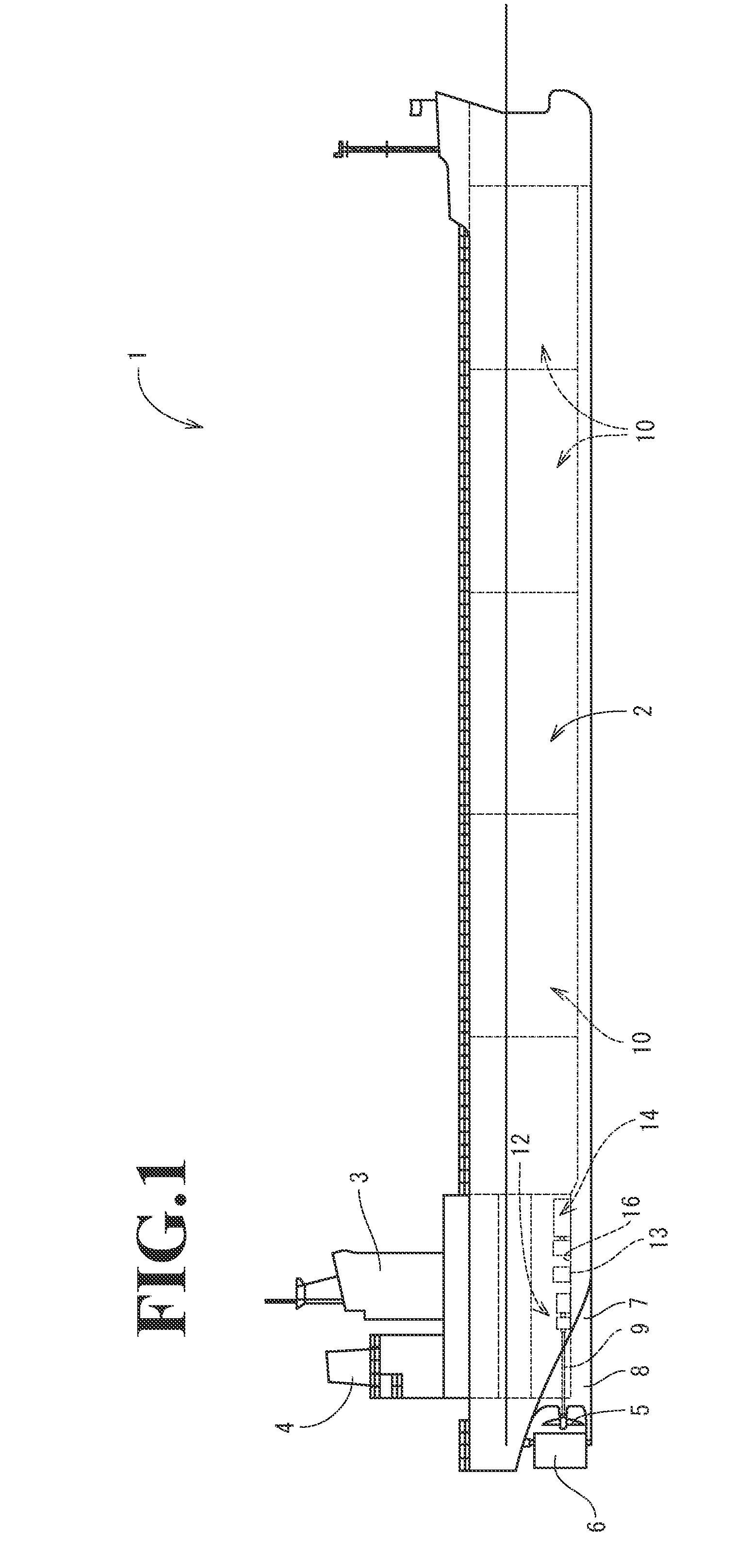
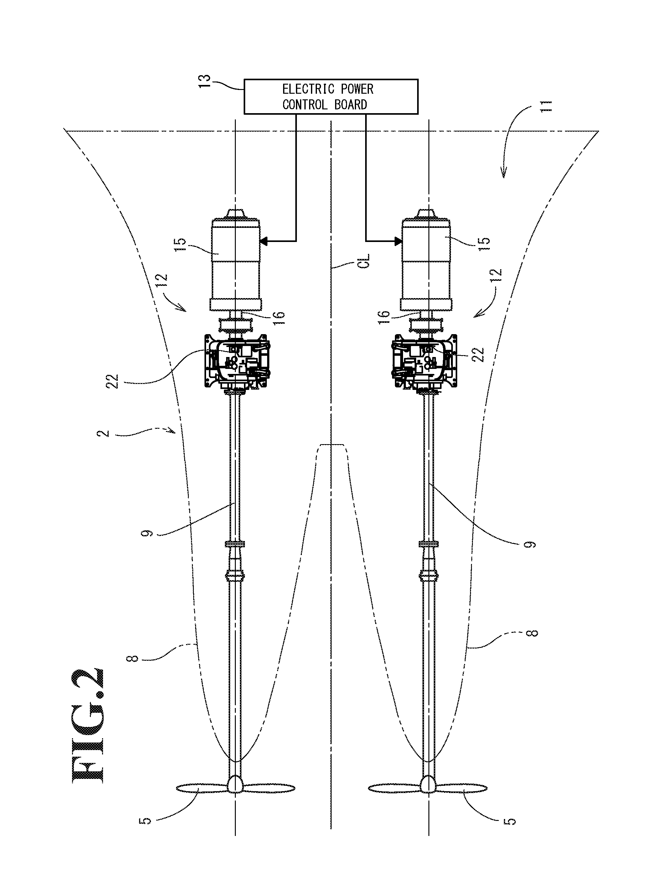
[0037]To begin with, the outline of the ship will be described. As illustrated in FIGS. 1 to 3, a ship 1 of the present embodiment includes a hull 2, a cabin 3 (bridge) provided on the side of the stern of the hull 2, a funnel 4 (smokestack) arranged in rear of the cabin 3, a pair of propellers 5 provided on the lower portion in rear of the hull 2, and a rudder 6. In this case, a pair of skegs 8 is integrally formed on a ship bottom 7 on the side of the stern. A propeller shaft 9 for drivingly rotating the propeller 5 is pivotally supported on each skeg 8. The skegs 8 are symmetrically formed with reference to a hull center line CL (see FIG. 3) that divides the hull 2 in the right-and-left width direction. That is, in the first embodim...


PUM


Abstract

An engine device executes the control of the opening degree of a main throttle valve when engine load is in a low load area. In contrast, when the engine load is in a medium-to-high load area, the engine device sets the main throttle valve to a predetermined opening degree and executes the control of the opening degree of an air supply bypass valve.

Description

CROSS-REFERENCE TO RELATED APPLICATIONS[0001]The present application is a continuation application of International Application No. PCT / JP2015 / 52200, filed Jan. 27, 2015, which claims priority to Japanese Patent Application No. 2014-035830, filed Feb. 26, 2014 and Japanese Patent Application No. 2014-035832, filed Feb. 26, 2014. The contents of these applications are incorporated herein by reference in their entirety.BACKGROUND OF THE INVENTION[0002]The present invention of the instant application relates to an engine device.[0003]Conventionally, for example, regarding ships such as tankers and transport vessels or power generation facilities on land, diesel engines have been utilized as the driving source thereof. However, much of toxic substances such as nitride oxides, sulfur oxides, particulate matter, which are impediments to environmental preservation, are included in the exhaust gas of the diesel engine. Accordingly, in recent years, gas engine devices and the like, which can...

Claims


Application Information

Patent Timeline
Patent Type & Authority Applications(United States)
IPC IPC(8): F02D41/00F02D11/10
CPCF02D11/10F02D41/0007B63B2241/22B63H21/17B63J3/04F02B19/12F02B29/0406F02B37/16F02D9/02F02D19/024F02D19/027F02D23/00F02D29/06F02D41/0002F02D41/0027F02D2200/0406F02M21/0284Y02T10/12Y02T10/30Y02T10/40F02D2700/0246
Inventor HAGIWARA, RYOICHIYAMAGISHI, OSAMU
Owner JAPAN SHIP MACHINERY & EQUIPMENT ASSOCIATION
Why Eureka
Try Eureka