System for supplying fuel to a turbomachine

a technology for turbomachines and fuel supply systems, which is applied in the direction of turbine/propulsion fuel valves, mechanical devices, machines/engines, etc., can solve the problems of reducing the efficiency of turbomachines, affecting the size and mass of fuel circuits, and not allowing to reach the maximum power gain, so as to achieve the effect of supplying the combustion chamber and minimizing the power drawn

Pending Publication Date: 2020-01-02
SN DETUDE & DE CONSTR DE MOTEURS DAVIATION S N E C M A
View PDF5 Cites 0 Cited by
  • Summary
  • Abstract
  • Description
  • Claims
  • Application Information

AI Technical Summary

Benefits of technology

[0023]With the flow rate measurement, the system can adapt the speed of the pump to provide an appropriate flow rate if necessary. Therefore, the system optimally takes advantage of the ability of its drive system to vary the pump speed and minimizes the power drawn to supply the combustion chamber with fuel.
[0024]Another advantage is that in established speed, the flow rate provided by the pump being adapted, there is no recirculation flow rate, as in a conventional solution. In addition, this fuel circuit can do without a metering unit, the function of which is provided by the flow rate sensor and means, generally electronic, to control the drive system device of the pump.
[0025]In addition, the concept allows to remove components of the hydromechanical group according to the state of the art, such as the regulating valve and a servo valve for controlling the metering unit, which represents a mass saving.

Problems solved by technology

The flow rate surplus injected by the pump 1 induces a surplus of power drawn on the accessory relay box 5 compared to the need, which is detrimental to the efficiency of the turbomachine.
This has a negative influence on the size and mass of the fuel circuit, especially for unrepresented heat exchangers placed to dissipate heat in this circuit.
It therefore does not allow to reach the maximum power gain made possible by a possible adaptation of the speed of the pump 1

Method used


Image

  • System for supplying fuel to a turbomachine
  • System for supplying fuel to a turbomachine
  • System for supplying fuel to a turbomachine

Examples


Embodiment Construction

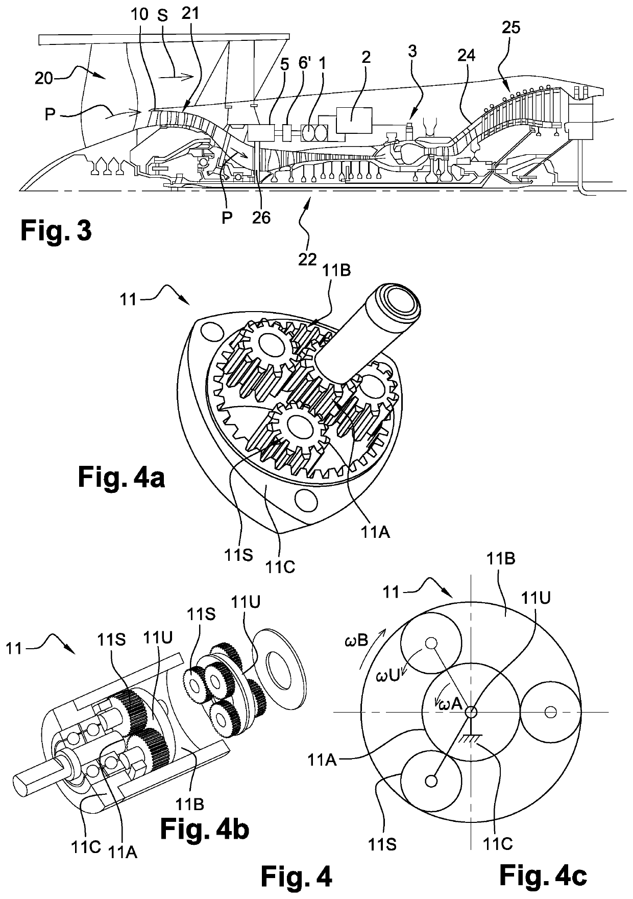
[0047]In a turbomachine, for example a dual flow turbomachine shown in FIG. 3, the outlet air flow at fan 20 is divided into a primary flow P entering the engine and a secondary flow S surrounding the latter. The primary flow then passes through low-pressure compressors 21 and high-pressure compressors 22, the combustion chamber 3 supplied by the fuel circuit mentioned previously, and then high-pressure turbines 24 and low-pressure turbines 25. Generally, all the high-pressure compressors 22 and high-pressure turbines 24 rotate as a unit on a common axis 26 and form the engine part of the turbomachine with the combustion chamber.

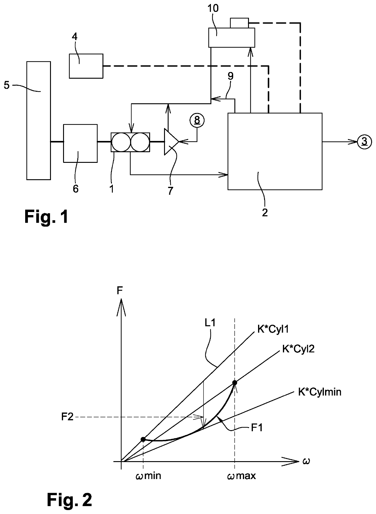
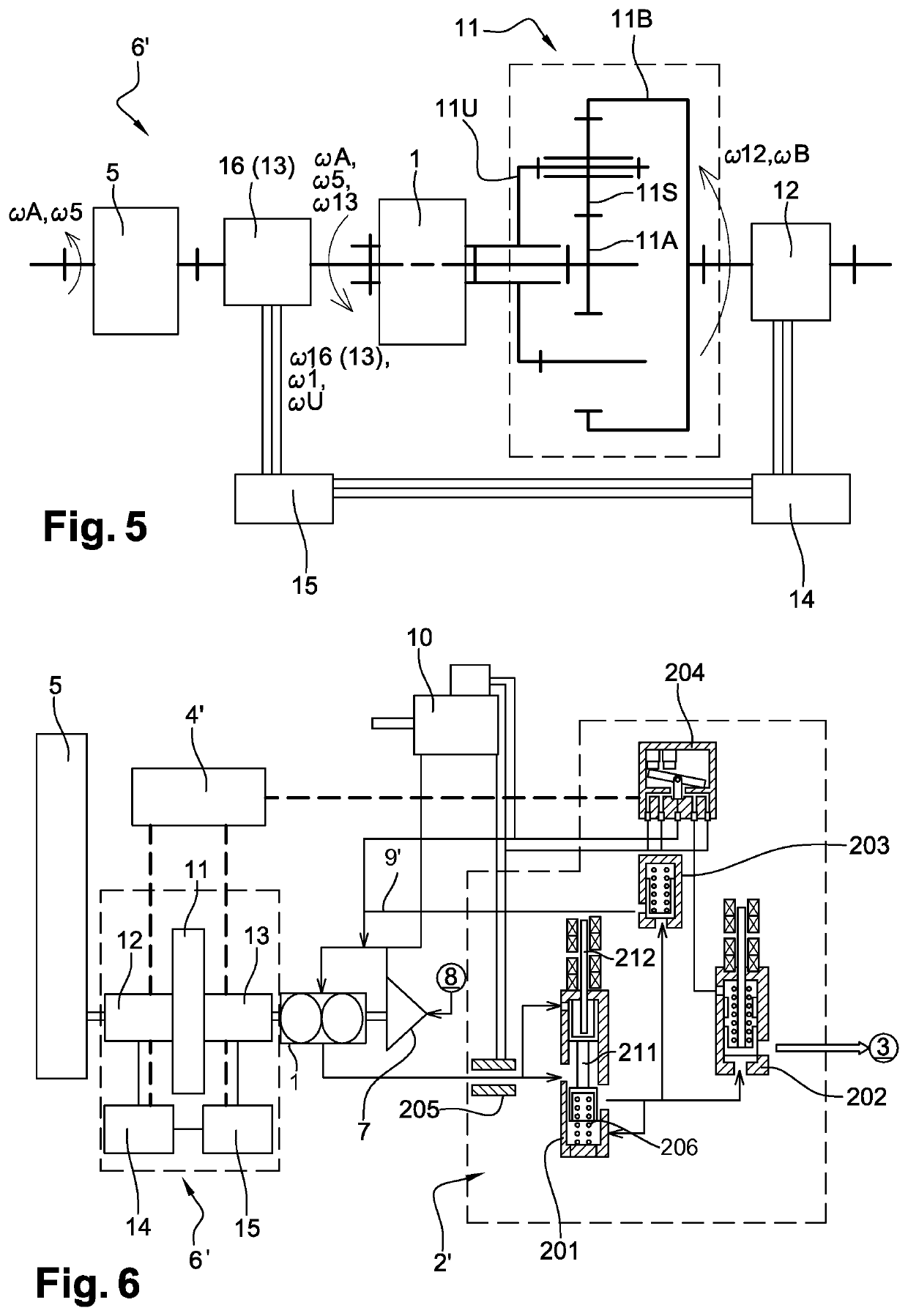
[0048]Generally, the drive shaft 26 drives the accessory relay box 5 which can include several gear trains connected to outlet shafts to drive various equipment units. Here one of the outlet shafts of the gearbox drives, by a drive device 6′, the volumetric pump 1 which supplies the hydromechanical group 2 injecting the fuel into the combustion chamber 3. Ge...


PUM


Abstract

The present disclosure relates to a system for supplying fuel to a turbomachine. In some embodiments, a fuel circuit includes a pressurisation valve at an outlet of the system and a pump. The circuit may include a flow rate sensor arranged between the outlet of the pump and the pressurisation valve. In some embodiments, the flow rate sensor may include a sliding drawer, a restoring spring, and a sensor for detecting the position of said drawer in order to indicate the flow passing through the flow rate sensor. The system may include a device arranged to drive the pump with a controllable rotational speed and a control configured to control the device on the basis of a measurement supplied by the flow rate sensor, in such a way as to adapt the rotational speed of the pump shaft.

Description

FIELD OF INVENTION[0001]This invention relates to the field of turbomachines. It concerns more particularly the fuel supply system and the regulation of the fuel flow rate in this circuit.BACKGROUND OF THE INVENTION[0002]The prior art includes in particular patent applications published under the numbers FR-A1-2 934 321, EP-A1-3 051 103 and FR-A1-3 035 155.[0003]Turbomachines installed on an aircraft are equipped with a circuit for supplying fuel, delivering fuel to the combustion chamber, which must be regulated as required according to flight conditions. With reference to FIG. 1, the fuel circuit generally includes a main high-pressure pump 1 of volumetric type that sends fuel to a hydromechanical group 2 before injection to the combustion chamber 3. The assembly is arranged to ensure, at the outlet to the combustion chamber, a fuel flow rate adapted to the need. A control box 4 usually controls the hydromechanical group 2 so that it adapts the flow rate sent by the pump 1 to the ...

Claims


Application Information

Patent Timeline
Patent Type & Authority Applications(United States)
IPC IPC(8): F02C7/232F02C7/236F02C7/32F02C9/30
CPCF05D2270/02F05D2270/3013F02C7/232F05D2260/40311F02C9/30F02C7/32F05D2270/3061F02C7/236
Inventor PORA, LOÏCDE WERGIFOSSE, HUGUETTE
Owner SN DETUDE & DE CONSTR DE MOTEURS DAVIATION S N E C M A
Why Eureka
Try Eureka