Eye-flow guiding level calculating system, eye-flow guiding level calculating program, and eye-flow guiding level calculating method

a level calculation and level calculation technology, applied in the field of eyeflow guiding level calculating system, eyeflow guiding level calculating program, eyeflow guiding level calculating method, can solve the problems of large-scale devices, difficult to predict the actual eye flow of the target reader, and high cos

Inactive Publication Date: 2005-06-16
SEIKO EPSON CORP
View PDF2 Cites 0 Cited by
  • Summary
  • Abstract
  • Description
  • Claims
  • Application Information

AI Technical Summary

Benefits of technology

[0090] According to this construction, the same advantages as those in the eye-flow guiding level calculating system of the exemplary embodiment 9 can be obtained.

Problems solved by technology

However, in the inventions described in Japanese Unexamined Patent Application Publication No. 2002-175290 and Japanese Unexamined Patent Application Publication No. 6-162, since the eye flow is detected using an apparatus, such as a camera, there are problems in that the process requires large-scale devices and a high cost is required.
Therefore, when the designer performs the layout through his own eye flow, it is difficult to predict an actual eye flow of the target readers.
Thus, there is a problem in that it is difficult to realize a readable layout.
However, if the given amount of image features does not match the established correspondence, a suitable eye flow cannot be obtained.
For this reason, there is a problem in that, even after establishing many correspondences, a sufficient reliability cannot be obtained.

Method used


Image

  • Eye-flow guiding level calculating system, eye-flow guiding level calculating program, and eye-flow guiding level calculating method
  • Eye-flow guiding level calculating system, eye-flow guiding level calculating program, and eye-flow guiding level calculating method
  • Eye-flow guiding level calculating system, eye-flow guiding level calculating program, and eye-flow guiding level calculating method

Examples


second exemplary embodiment

[0192] Next, a second exemplary embodiment of the present invention will be described with reference to the drawings. FIGS. 16 to 19 are diagrams showing the second exemplary embodiment of the eye-flow guiding level calculating system, the eye-flow guiding level calculating program, and the eye-flow guiding level calculation method according to exemplary embodiments of the present invention.

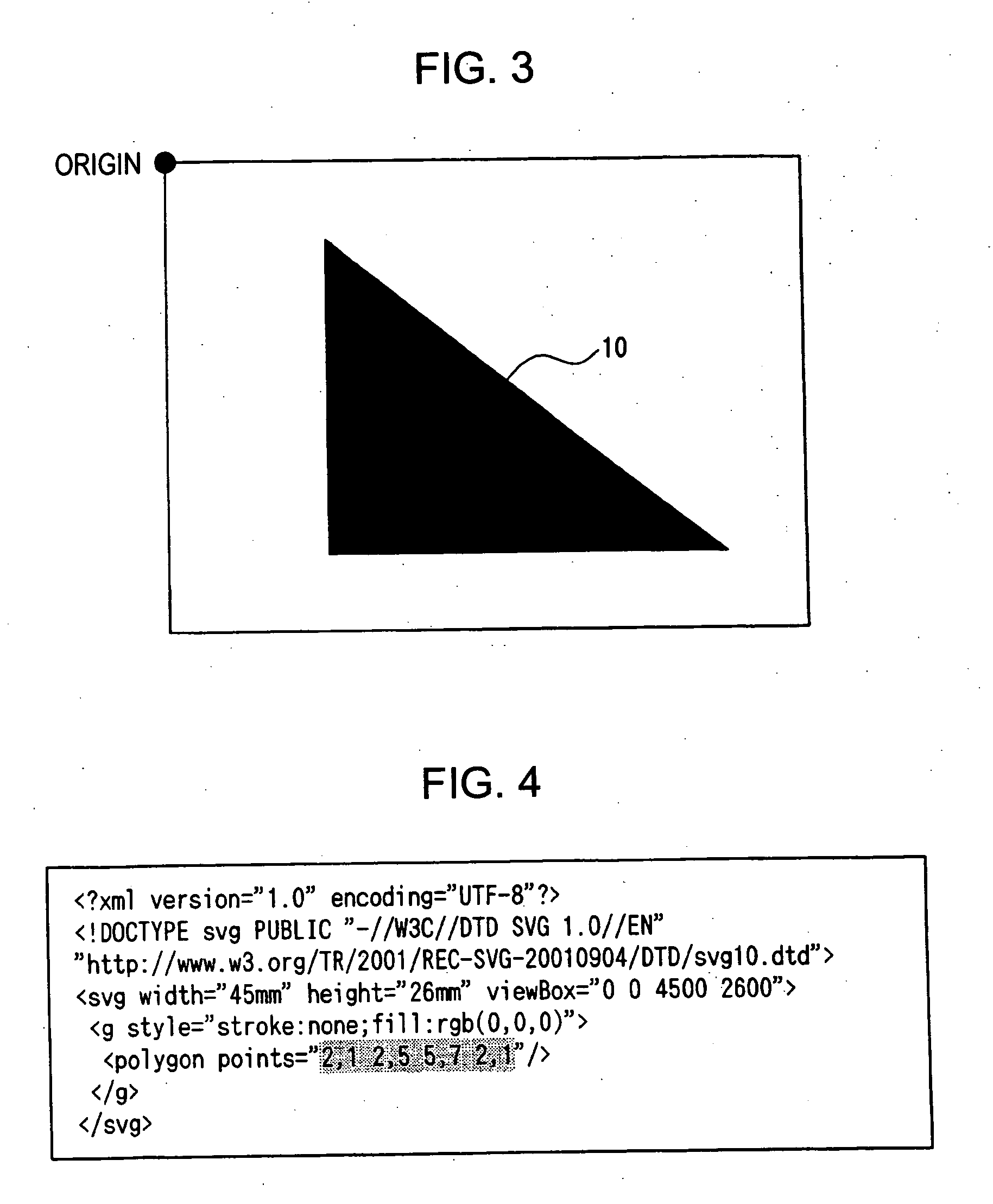
[0193] The present exemplary embodiment relates to the application of the eye-flow guiding level calculating system, the eye-flow guiding level calculating program, and the eye-flow guiding level calculating method according to embodiments of the present invention to a case in which the direction and intensity of guiding the eye-flow of the image object 10 are calculated. The present exemplary embodiment is different from the first exemplary embodiment in that the distance from a sideline opposite to the guiding reference point among the outer line of the image object 10 (hereinafter, referred t...

third exemplary embodiment

[0215] Next, a third exemplary embodiment of the present invention will be described with reference to the drawings. FIGS. 20 to 28 are diagrams showing the third exemplary embodiment of the eye-flow guiding level calculating system, the eye-flow guiding level calculating program, and the eye-flow guiding level calculation method according to exemplary embodiments of the present invention.

[0216] The present exemplary embodiment relates to the application of the eye-flow guiding level calculating system, the eye-flow guiding level calculating program, and the eye-flow guiding level calculating method according to exemplary embodiments of the present invention to a case in which the direction and intensity of guiding the eye-flow of the image object 10 are calculated. The present exemplary embodiment is different from the first and second exemplary embodiments in that the eye-flow guiding direction and the eye-flow guiding intensity are calculated from a raster image having the image...

fourth exemplary embodiment

[0249] Hereinafter, a fourth exemplary embodiment of the present invention will be described with reference to the drawings. FIGS. 29 to 33 are diagrams showing the fourth exemplary embodiment of the eye-flow guiding level calculating system, the eye-flow guiding level calculating program, and the eye-flow guiding level calculation method according to exemplary embodiments of the present invention. Further, in the present exemplary embodiment, FIGS. 1 and 3 to 12, which are common to the first exemplary embodiment, are used for the description.

[0250] The present exemplary embodiment relates to the application of the eye-flow guiding level calculating system, the eye-flow guiding level calculating program, and the eye-flow guiding level calculating method according to exemplary embodiments of the present invention to a case in which the direction and intensity of guiding the eye-flow of the image object are calculated.

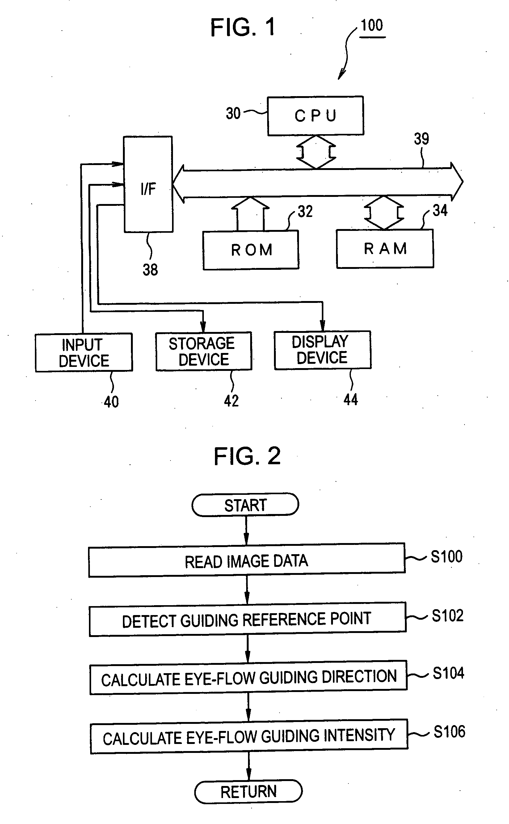
[0251] First, a construction of a layout device 100 to which exe...


PUM


Abstract

Exemplary embodiments of the invention provide an eye-flow guiding level calculating system which can plan miniaturization and low cost of a device and surely obtain a suitable eye flow. A layout device, first, detects each vertex of an image object as guiding reference points, based on vector image data. And then, for every guiding reference point, two auxiliary lines are virtually formed to intersect the guiding reference point along an outline of the image object. Subsequently, the direction in which a bisector line of an obtuse angle among angles, made by the virtual auxiliary lines, extends outward from the guiding reference point is calculated as an eye-flow guiding direction. Further, for every guiding reference point, the distance from the center G of the image object up to the guiding reference point is calculated as an eye-flow guiding intensity. According to this construction, it is possible to quantitatively calculate in which direction the image object tends to guide the eye-flow.

Description

BACKGROUND OF THE INVENTION [0001] 1. Field of Invention [0002] Exemplary embodiments of the present invention relates to a system, a program, and a method of calculating a degree of guiding an eye-flow of an image. More specifically, exemplary embodiments of the present invention relate to an eye-flow guiding level calculating system, an eye-flow guiding level calculating program, and to an eye-flow guiding level calculating method, capable of miniaturizing system devices and decreasing the cost thereof, while effectively enabling a suitable eye flow for the eye-flow of images. [0003] 2. Description of Related Art [0004] Like a typical consumer catalog of goods, a document having an optimum layout design, in which layout elements (for example, a title, an image, and a text) are arranged to be readily noticeable, is commonly referred to as a “visual document.” The creation of the visual documents requires a significant amount of specialized knowledge, and thus it is difficult for an...

Claims


Application Information

Patent Timeline
Patent Type & Authority Applications(United States)
IPC IPC(8): G06T1/00G01C9/00G06F15/00G06F17/00G06T7/60
CPCG06T7/606G06T7/66
Inventor KAYAHARA, NAOKINAGAHARA, ATSUSHI
Owner SEIKO EPSON CORP
Why Eureka
Try Eureka