Gas manifold

Pending Publication Date: 2021-09-23
RINNAI CORP
View PDF2 Cites 0 Cited by
  • Summary
  • Abstract
  • Description
  • Claims
  • Application Information

AI Technical Summary

Benefits of technology

[0009]However, recent combustion apparatuses may perform switching between more sets of burners to regulate the thermal power more precisely. In this case, feeding each distribution chamber with fuel gas at an appropriate flow rate has become more difficult for the reasons described below. More sets of switchable burners mean more distribution chambers included in the gas manifold. The number of burners fed with fuel gas from each distribution chamber is set differently for each distri

Problems solved by technology

In this case, feeding each distribution chamber with fuel gas at an appropriate flow rate has become more difficult for the reasons described bel

Method used


Image

  • Gas manifold
  • Gas manifold
  • Gas manifold

Examples


Embodiment Construction

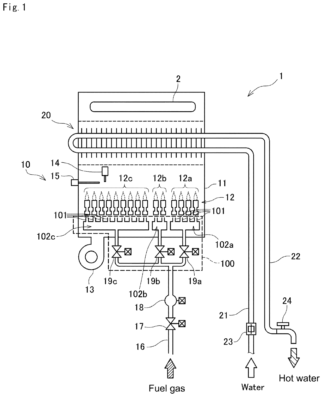
[0033]FIG. 1 is a diagram of a water heater 1 including a combustion apparatus 10. The water heater 1 includes the combustion apparatus 10 that burns fuel gas, and a heat exchanger 20 that uses hot combustion gas generated in the combustion apparatus 10 to produce hot water. The heat exchanger 20 is connected to a water supply channel 21 that receives service water, and a hot-water supply channel 22 that feeds the hot water produced in the heat exchanger 20. The water supply channel 21 has, on its course, a flow sensor 23 that detects the flow rate of service water flowing into the heat exchanger 20. In addition, the hot-water supply channel 22 has a hot-water supply faucet 24 connected to its end.

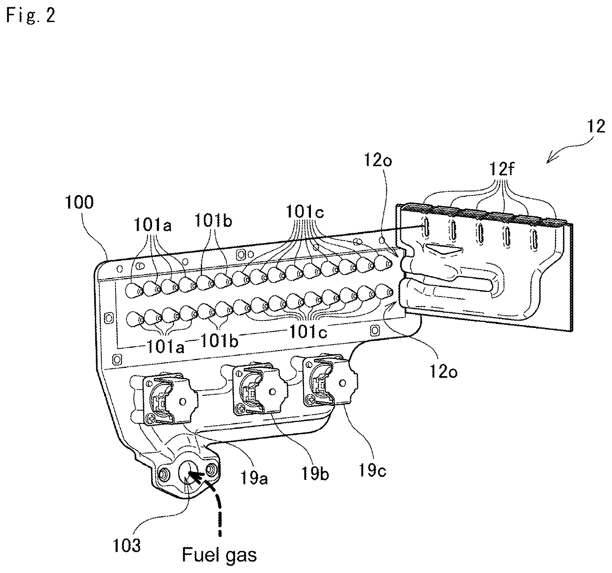
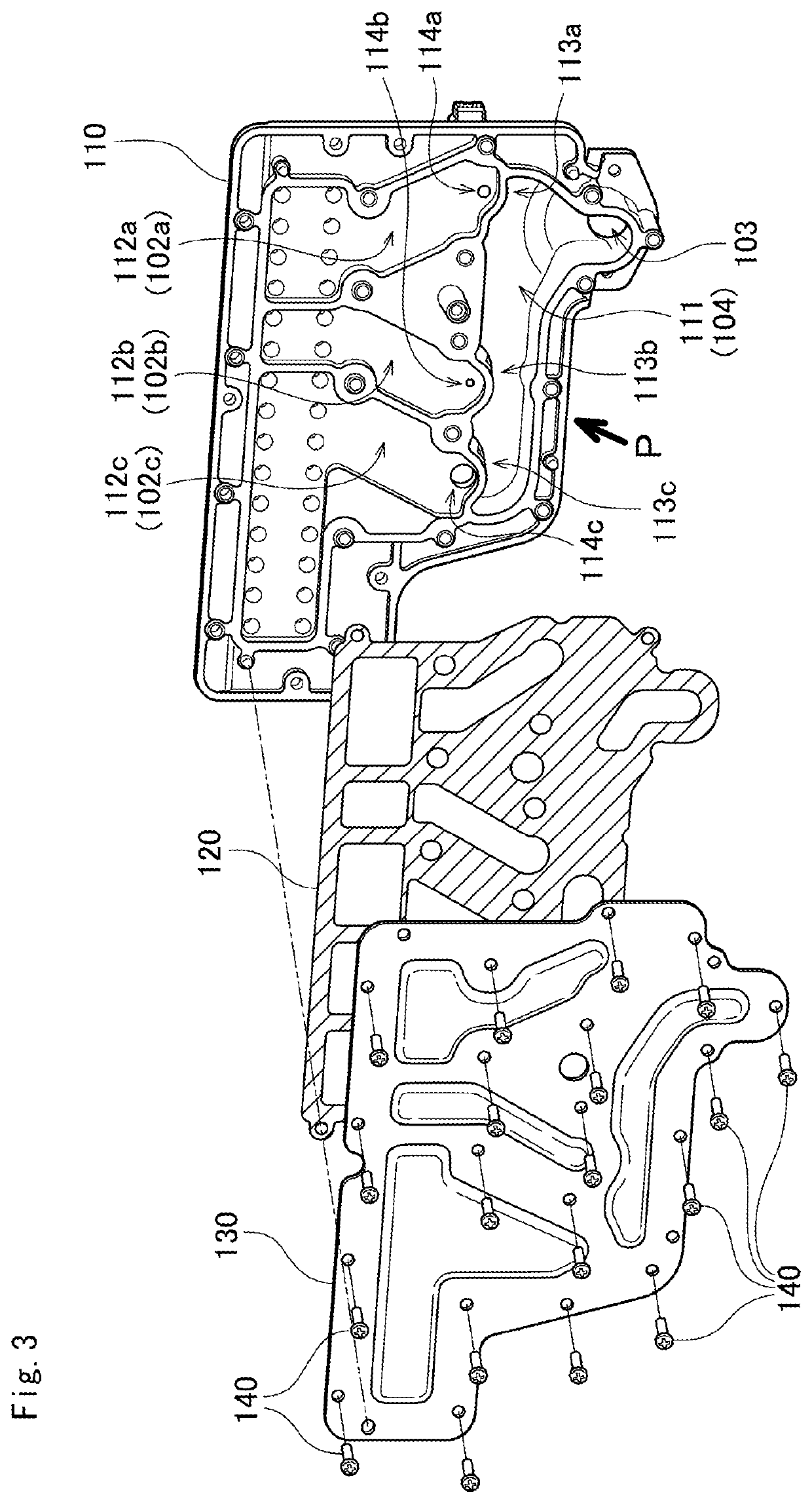
[0034]The combustion apparatus 10 includes a combustion case 11 that defines a combustion chamber in its inner space, a plurality of burners 12 installed in the combustion case 11, a gas manifold 100 that feeds the burners 12 with fuel gas, a combustion fan 13 that feeds the combustion cas...


PUM


Abstract

A gas manifold allows each distribution chamber to be fed with fuel gas at an appropriate flow rate irrespective of an increase in the number of distribution chambers included in the gas manifold. Fuel gas flowing through in an inlet is distributed to a plurality of distribution chambers through a main channel. A bypass channel parallel with the main channel also feeds fuel gas to a maximum distribution chamber. This can prevent the feeding of the fuel gas to the maximum distribution chamber from being affected by and reduced by the feeding of the fuel gas to the bypassed distribution chambers. This also prevent the feeding of the fuel gas to the other distribution chambers from being affected by and reduced by the feeding of the fuel gas to the maximum distribution chamber. The plurality of distribution chambers are thus fed with fuel gas at appropriate flow rates.

Description

BACKGROUND OF INVENTIONField of the Invention[0001]The present invention relates to a gas manifold for distributing fuel gas to a plurality of burners in a combustion apparatus that performs stepwise switching of the number of burners to burn the fuel gas among the plurality of burners included in the combustion apparatus.Background Art[0002]Hot-water supply systems and heating systems incorporate a combustion apparatus for burning fuel gas. The combustion apparatus includes a plurality of burners that are individually fed with fuel gas through their corresponding nozzles. The combustion apparatus also performs stepwise switching of the number of burners to burn the fuel gas. In accordance with intended thermal power, the apparatus increases or decreases the number of burners to be used for burning the fuel gas.[0003]Each burner is fed with fuel gas through the corresponding nozzle. Thus, stepwise switching of the number of burners to burn the fuel gas involves stepwise switching of...

Claims


Application Information

Patent Timeline
IPC IPC(8): F02C7/228F02C7/22F23D14/48F02C7/232
CPCF02C7/228F02C7/222F23K5/00F02C7/232F23D14/48F23D2900/14641F23D2900/14003F23D14/045F24H1/00
Inventor SHICHI, KAZUYUKIKATAOKA, KUNIO
Owner RINNAI CORP
Why Eureka
Try Eureka