Microphone system

a microphone and microphone technology, applied in the direction of transducer details, electrical transducers, electrical apparatus, etc., can solve the problems of unavoidable deterioration of the foregoing recognition capability, inability to significantly improve and the sn ratio of the voice signal will hardly be improved, so as to achieve the effect of improving the sn ratio of the voice signal

Inactive Publication Date: 2006-12-05
ALPINE ELECTRONICS INC
View PDF17 Cites 66 Cited by
  • Summary
  • Abstract
  • Description
  • Claims
  • Application Information

AI Technical Summary

Benefits of technology

[0024]Therefore, it is an object of the invention to provide a microphone system (noise reduction system) using two microphones that improves the SN ratio of the voice signal.

Problems solved by technology

Accordingly, inside a car's passenger compartment filled with various noises (engine noise, road noise, pattern noise, whistling noise, etc.) that a running car creates, the deterioration of the foregoing recognition capability is unavoidable.
This is a significant problem when incorporating a voice recognition system in a car.
However, if the adaptive filter coefficient W is determined so as to satisfy the expression (2), the voice will not be damaged, but on the other hand, the noise will hardly be eliminated either and the SN ratio will hardly be improved, which is a problem to be solved.
Therefore, in the conventional microphone system, the SN ratio of the voice signal cannot be improved significantly, which is disadvantageous.

Method used


Image

  • Microphone system
  • Microphone system
  • Microphone system

Examples


first embodiment

1. First Embodiment

[0053](a) Configuration of the Microphone System

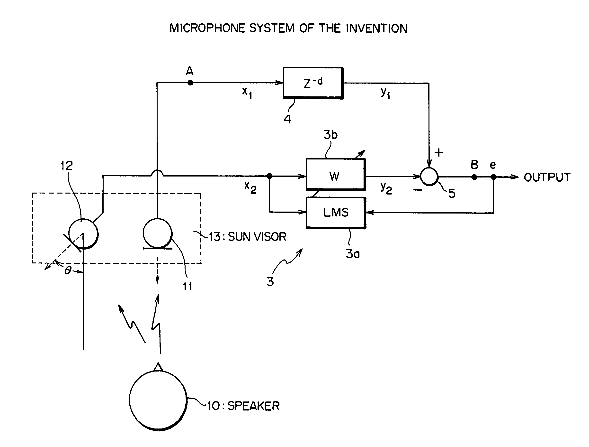
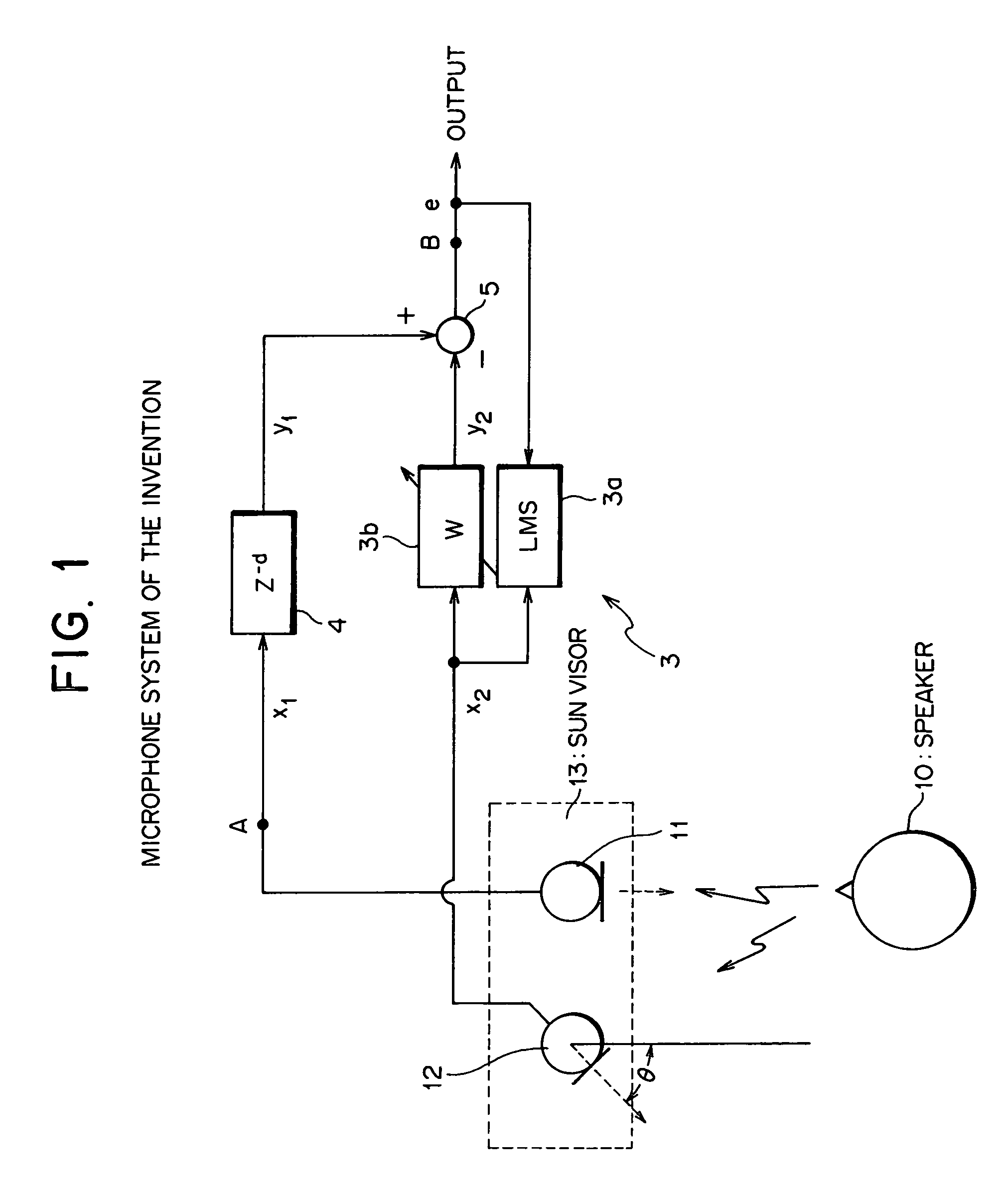
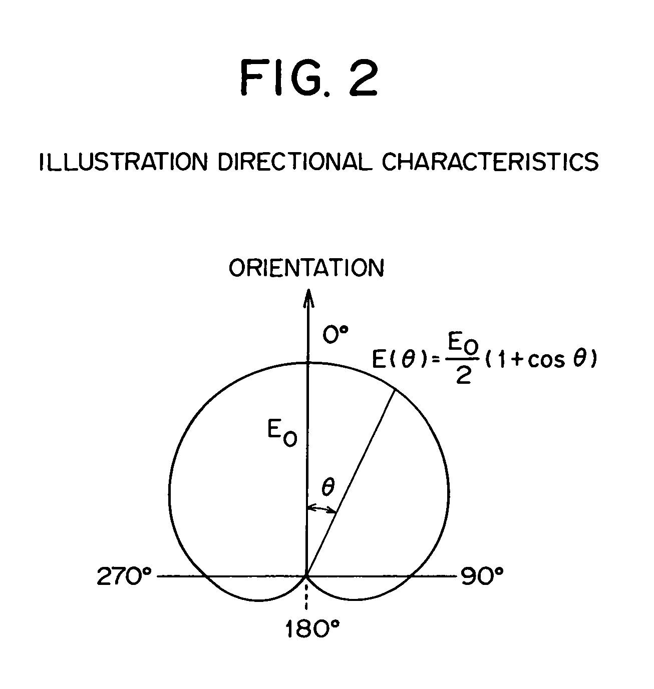
[0054]FIG. 1 illustrates a configuration of the microphone system relating to the first embodiment of the invention, in which the same symbols are applied to the same components as in FIG. 17. In FIG. 1, 10 signifies a speaker, for example, a driver of a car, and 11, 12 signify first and second microphones having directional characteristics as to the voice reception sensitivity. The directional characteristics of the microphones have a unidirectional sensitivity characteristic, as shown in FIG. 2. That is, when the orientation is given by θ=0°, and the sensitivity at θ=0° is given by E0, the sensitivity at an arbitrary angle θ is expressed by the following equation:

E(θ)=E0(1+cosθ) / 2

and the sensitivity of the microphone decreases as the direction of the microphone deviates from the orientation θ=0°.

[0055]As an example, the first and second microphones 11, 12 in FIG. 1 are mounted on the sun visor 13 above the driver's...

second embodiment

2. Second Embodiment

[0082](a) Configuration of the Microphone System

[0083]FIG. 8 illustrates another configuration of the microphone system relating to the second embodiment of the invention, in which the same symbols are applied to the same components as in FIG. 1. The difference lies in that the target response setter 4 in FIG. 1 is configured by an adaptive signal processor 4′ in FIG. 8. In the microphone system in FIG. 1, only the adaptive signal processor 3 executes the adaptive signal processing to minimize the power of the error signal e; however in the microphone system in FIG. 8, the adaptive signal processor 3 and the adaptive signal processor 4′ execute the adaptive signal processing to minimize the power of the error signal e.

third embodiment

3. Third Embodiment

[0084](a) Configuration of the Microphone System

[0085]FIG. 9 illustrates another configuration of the microphone system relating to the third embodiment of the invention, in which the same symbols are applied to the same components as in FIG. 1. In the drawing, 10 signifies the driver of a car, and 11, 12 signify the first and second microphones. The first microphone 11 is installed on the ceiling right above the face of the speaker 10, and the second microphone 12 is installed on the ceiling on the occipital side about 1 to 5 cm from the first microphone position.

[0086]3 signifies an adaptive signal processor which receives an error signal e and an output signal x2 from the microphone 12 as the reference signal, and executes the adaptive signal processing on the basis of the LMS (Least Mean Square) algorithm so as to minimize the power of the error signal e. In the adaptive signal processor 3, 3a signifies an LMS calculator, 3b an adaptive filter with a configura...


PUM


Abstract

The microphone system of the invention executes an adaptive filter processing by using output signals from two microphones to output a speaker's voice signal with an improved SN ratio, in which the two microphones are laid out close to each other, and the angles formed by the orientations of the microphones with respect to the speaker's vocalizing direction are made different for each of the microphones. For example, the microphones are mounted on the sun visor of a vehicle, or on the ceiling above the front passenger seat or the driver's seat of the vehicle, with the orientations of the microphones differentiated. Further, the SN ratio of the output signal from one microphone is raised, and the SN ratio of the output signal from the other microphone is lowered. For example, one microphone is positioned right above a speaker's face, and the other microphone is spaced apart on the occipital side by about 1 to 5 cm from the position of the first microphone. Thus, the microphone system improves the SN ratio of the voice signal.

Description

BACKGROUND OF THE INVENTION[0001]1. Field of the Invention[0002]The present invention relates to a microphone system that executes an adaptive signal processing by using signals outputted from two microphones and outputs a speaker's voice signal with the signal to noise ratio improved.[0003]2. Related Art[0004]The technological development of voice recognition systems at present has evolved to such a level that a recognition rate of about 95% can be achieved in an environment that the SN (signal to noise) ratio of more than 15 dB is obtained. However, the conventional voice recognition system has the property that as the SN ratio is lowered by the surrounding noises, the recognition rate sharply decreases. FIG. 16 illustrates the relationship between the SN ratio and the recognition capability of some types of microphones (omni-directional, unidirectional, narrow-directional, AMNOR (Adaptive Microphone-array for Noise Reduction)), in which the relationship between the SN ratio and t...

Claims


Application Information

Patent Timeline
Patent Type & Authority Patents(United States)
IPC IPC(8): H04R3/00
CPCH04R3/005
Inventor SAITO, NOZOMUKIUCHI, SHINGONAKATA, KOICHI
Owner ALPINE ELECTRONICS INC
Why Eureka
Try Eureka