Check patentability & draft patents in minutes with Patsnap Eureka AI!

Electric Recessible Track Assembly and Method of Installation in Standard 5/8-inch Thick Drywall

a technology of recessible track and drywall, which is applied in the direction of lighting device details, lighting support devices, lighting and heating apparatus, etc., can solve the problems of insufficient illumination of an area by lighting, inability to easily move recessed lights, and drawbacks of visible tracks

Inactive Publication Date: 2019-06-13
PUREEDGE LIGHTING LLC
View PDF1 Cites 0 Cited by
  • Summary
  • Abstract
  • Description
  • Claims
  • Application Information

AI Technical Summary

Benefits of technology

The patent describes an improved track lighting system that solves previous problems. The system includes an extruded track with bus rods and fixture retention channels, as well as a channel cover for aesthetic purposes. The system is easy to install and can be powered by either AC or DC power sources. The method for recessing track lighting involves creating an opening in a surface, placing the track within the opening, securing the flanges to the surface, and then mounting a light fixture within the track. The technical effects of this invention include improved aesthetics, easier installation, and more flexibility in power source options.

Problems solved by technology

However, it is not enough that the lighting provides sufficient illumination to an area.
However, the visible track has drawbacks when the aesthetics are important.
However, recessed lights are fixed light sources which cannot be readily moved without some skilled electrical re-wiring and surface patching.
Another drawback is recessing the lights requires that either the lights be positioned either joists or the joist must be notched or altered in some way to accommodate the light.
The cutting of ceiling joists is an undesirable option in many cases.
Until the invention of the present application, these and other problems in the prior art went either unnoticed or unsolved by those skilled in the art.

Method used


Image

  • Electric Recessible Track Assembly and Method of Installation in Standard 5/8-inch Thick Drywall
  • Electric Recessible Track Assembly and Method of Installation in Standard 5/8-inch Thick Drywall
  • Electric Recessible Track Assembly and Method of Installation in Standard 5/8-inch Thick Drywall

Examples


Embodiment Construction

[0035]While this invention is susceptible of embodiments in many different forms, there is shown in the drawings and will herein be described in detail at least one preferred embodiment of the invention with the understanding that the present disclosure is to be considered as an exemplification of the principles of the invention and is not intended to limit the broad aspect of the invention to any of the specific embodiments illustrated.

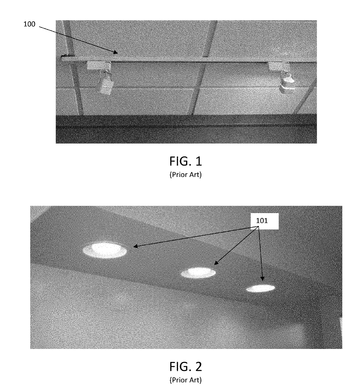
[0036]With reference to the lighting systems of FIGS. 1 and 2, a standard track lighting system and recessed lighting can be seen. The benefits of the present assembly and method over these prior art systems are significant. The track lighting system 100 of FIG. 1 allows the two light fixtures to be moved along the track to desired positions. However, the system 100 lacks favorable aesthetics, due to its exposed industrial-like track, and provides an obstacle to painting. Further, adding a third light fixture, or replacing one of the two existing fix...


PUM


Abstract

A recessible track for a lighting system, the track including a channel defined by first and second opposing sidewalls, a base wall, and a longitudinal opening opposite the base wall, a first lateral flange extending laterally from an exterior of the first sidewall substantially parallel to the base wall and for at least a portion of the length of the track, and a second lateral flange extending from an exterior of the second sidewall substantially parallel to the base wall and for at least a portion of the length of the track. The channel is dimensioned such that it does not extend past a thickness of standard ⅝-inch drywall when recessed while the first and second lateral flanges secure the channel to the surface. The flanges may be concealed by blending with the drywall using a concealing material such as a joint compound or the like.

Description

RELATED APPLICATIONS[0001]This application is a continuation application of U.S. patent application Ser. No. 15 / 838,616 titled “Electric Recessible Track Assembly and Method of Installation in Standard ⅝-inch Thick Drywall” and filed Dec. 12, 2017, now U.S. Pat. No. ______. The '616 application is hereby incorporated by reference.TECHNICAL FIELD OF THE INVENTION[0002]The present invention relates to track lighting and recessed lighting. Specifically, the invention relates to a method and system for recessing track lighting into a drywall surface, such as a ceiling or wall. Most specifically, installation of the disclosed system is in standard ⅝-inch thick drywall.BACKGROUND OF THE INVENTION[0003]Lighting is an important feature when designing work or living space. However, it is not enough that the lighting provides sufficient illumination to an area. The lighting fixtures have an aesthetic function as well. Two common permanent lighting fixtures are known as track lighting and rece...

Claims


Application Information

Patent Timeline
Patent Type & Authority Applications(United States)
IPC IPC(8): F21V21/04F21V21/005
CPCF21V21/048F21V21/005F21V21/30F21V21/35
Inventor KAY, GREGORY L.
Owner PUREEDGE LIGHTING LLC
Features
  • R&D
  • Intellectual Property
  • Life Sciences
  • Materials
  • Tech Scout
  • Unparalleled Data Quality
  • Higher Quality Content
  • 60% Fewer Hallucinations
Learn More