
Interventional ablation device with tissue discriminating capability

a tissue discrimination and ablation device technology, applied in the field of interventional ablation devices, can solve the problems of cell death, tumor cell destruction, and inability to complete the removal, and achieve the effect of simple and cost-effective monitoring of the ablation procedur

Inactive Publication Date: 2019-06-20
KONINKLJIJKE PHILIPS NV
View PDF3 Cites 0 Cited by
  • Summary
  • Abstract
  • Description
  • Claims
  • Application Information

AI Technical Summary

Benefits of technology

The present invention is about an interventional ablation device that can detect physiological information of tissue surrounding the device using sensors, and use this information to discriminate the type of tissue near the device (normal, tumorous, or ablated). This information can be provided to a surgeon or used automatically to control the ablation procedure, ensuring complete destruction of the tumor without affecting adjacent healthy tissue. The invention includes at least two sensors placed at opposing sides of the ablation element, which allows for monitoring of the ablation progression in both directions. This technology is simple and cost-effective, and can provide valuable information during interventional ablation procedures.

Problems solved by technology

For example, in the liver when there are plural tumor sites, complete removal may not be possible when these sites are present in different parts of the liver.
The heat in turn may induce cell death and hence may result in the destruction of tumor cells.
However, heat propagation may be difficult to predict because it may depend strongly on morphology of the heated tissue and whether for instance blood vessels acting as a heat sink are present.
Therefore, it may be almost impossible for a surgeon to tell whether a tumor has been completely treated, especially because such ablation progression generally is not visible under normal ultrasound vision.
However, the alternative of using magnetic resonance imaging (MRI) for guidance of the ablation needle could make the intervention very costly and impractical because then during the surgical intervention such surgery equipment needs to be available.

Method used


Image

  • Interventional ablation device with tissue discriminating capability
  • Interventional ablation device with tissue discriminating capability

Examples


Embodiment Construction

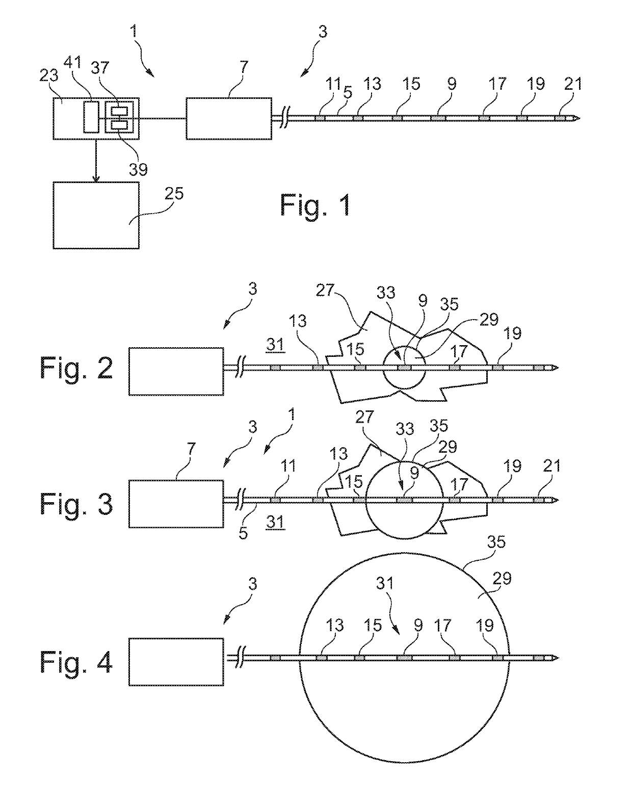
[0025]FIG. 1 shows an interventional ablation device 1 according to an embodiment of the present invention. The ablation device 1 may be used for example to ablate, i.e. remove or destroy, e.g. malicious tissue such as tumorous tissue enclosed by healthy tissue.

[0026]The ablation device 1 comprises an ablation needle 3 having an elongated body 5 and a handle 7. The elongated body 5 has a small diameter of e.g. between 22 and 11 gauge i.e. 0.72 and 3.05 mm and a length of e.g. between 100 and 300 mm or even more preferred between 120 and 250 mm. Furthermore, the elongated body 5 has a pointed tip at a distal end thereof thereby enabling to introduce the ablation needle easily into a patient's tissue.

[0027]An ablation element 9 is arranged on the body 5. The ablation element 5 is arranged in a region close to the distal end of the body 5 but spaced apart from this distal end. For example, the ablation element may be arranged at a distance between 5 and 100 mm away from the distal end ...


PUM


Abstract

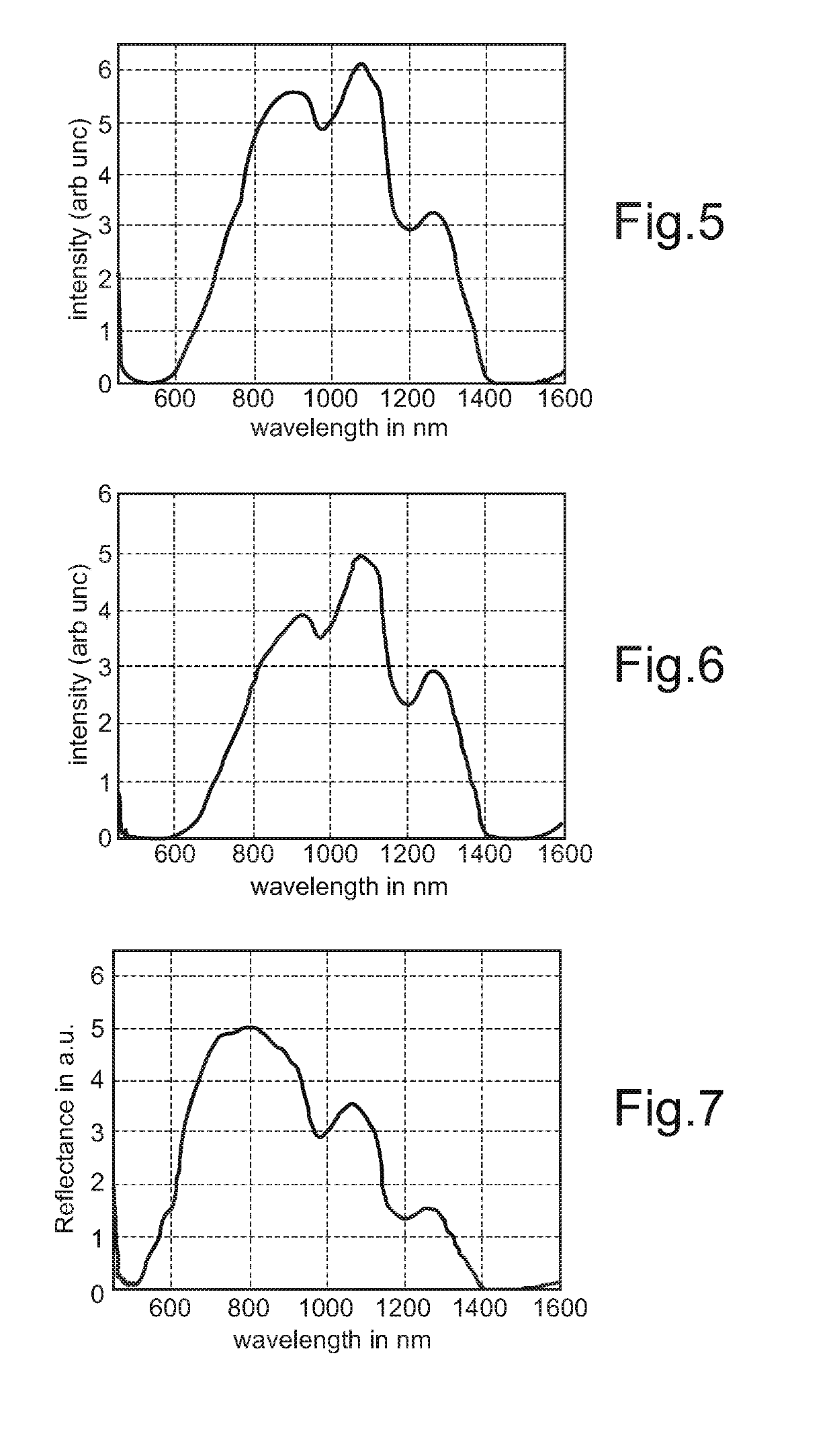
An interventional ablation device (1) is proposed to comprise an ablation needle (3) with an elongated body (5) and a handle (7). Adjacent to an ablation element (9) provided on the body (5), at least one or preferably two or more sensors (11-21) are provided, preferably at both of opposing sides of the ablation element (9). The ablation device (1) is adapted for detecting physiological information of tissue (27, 29, 31) surrounding an ablation site (33) based on measurement values provided by the sensors. E.g., optical sensors may be used to measure a reflectance spectrum indicating whether the adjacent tissue is healthy tissue (31), tumorous tissue (27) or ablated tissue (29). Using such information, an ablation process may be controlled.

Description

CROSS-REFERENCE TO PRIOR APPLICATIONS[0001]This application is a continuation of prior application Ser. No. 13 / 578,883, filed Aug. 14, 2012. Ser. No. 13 / 578,883 is a U.S. National Phase application under 35 U.S.C. § 371 of International Application Serial No. 2011IB50727, filed on Feb. 22, 2011, which claims the benefit of European Patent Application No. 20100154770, filed on Feb. 26, 2010. These applications are hereby incorporated by reference herein.FIELD OF THE INVENTION[0002]The present invention relates to an interventional ablation device which may be used for example for ablating tumorous tissue within a body of a patient. Furthermore, the present invention relates to an interventional ablation needle, to a computer program element enabling to control an ablation procedure and a computer readable medium with such computer program element.BACKGROUND OF THE INVENTION[0003]In oncology ablation of tumors is a common procedure especially in cases where resection of the tumor is d...

Claims


Application Information

Patent Timeline
Patent Type & Authority Applications(United States)
IPC IPC(8): A61B18/14A61B5/00
CPCA61B18/1477A61B5/0084A61B2034/2063A61B2018/00577A61B2017/00106A61B2017/00084A61B5/0066A61B2017/00057A61B18/02A61B8/0841A61B5/0075A61B2090/378A61B2017/00061
Inventor HENDRIKS, BERNARDUS HENDRIKUS WILHELMUSLUCASSEN, GERHARDUS WILHELMUSNACHABE, RAMIBIERHOFF, WALTHERUS CORNELIS JOZEFDESJARDINS, ADRIEN EMMANUEL
Owner KONINKLJIJKE PHILIPS NV
Learn More