Camera capable of automatically compensating focal length

a technology of automatic compensating and focal length, applied in the field of cameras, can solve the problems that the focus position of the camera known to the inventor may easily have unwanted movements, and achieve the effect of keeping the quality of the imag

Active Publication Date: 2019-06-27
CHICONY ELECTRONICS
View PDF0 Cites 4 Cited by
  • Summary
  • Abstract
  • Description
  • Claims
  • Application Information

AI Technical Summary

Benefits of technology

[0006]Based on the above, when a thermal source is applied to the camera according to one or some embodiments of the instant disclosure, e.g., when the camera generates heat due to the operation of the camera itself or when the camera is heated due to sun illumination, the first ring of the adjust seat can have a first axial thermal deformation and the second ring can have a second axial thermal deformation with a direction opposite to the first axial thermal deformation. Hence, the first axial thermal deformation and the second axial thermal deformation can compensate the thermal deformation of the components inside the camera (e.g., the lens barrel, the base, the circuit board). Therefore, the distance between the lens and the optical sensing member can be retained after the thermal source is applied to the camera, and the focal length for displaying an image can be maintained to keep the quality of the image.

Problems solved by technology

However, due to the change of temperature, the focus position of the camera known to the inventor may easily have unwanted movements.
These conditions may possibly result the focus position of the camera to be shifted to affect the photographic resolution of the image.

Method used


Image

  • Camera capable of automatically compensating focal length
  • Camera capable of automatically compensating focal length
  • Camera capable of automatically compensating focal length

Examples


second embodiment

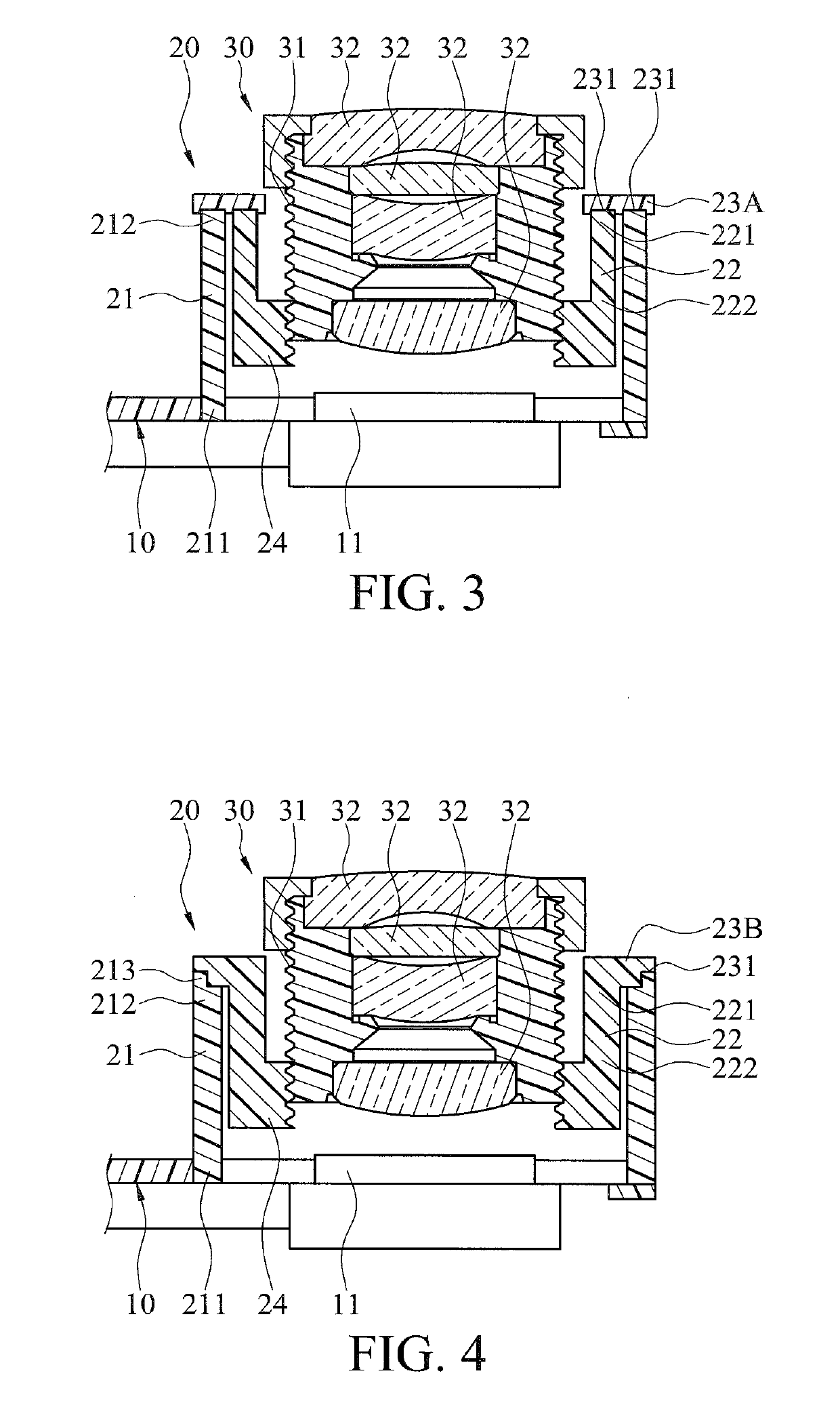
[0023]In some embodiments, the connecting member 23 of the camera 1 may have different configurations. For example, FIG. 3 illustrates an exploded view of a camera 1 according to the instant disclosure. In this embodiment, the connecting member 23A is an individual component and fixed on an end surface of the second end 212 of the first ring 21 and on an end surface of the third end 221 of the second ring 22. Since the connecting member 23A is fixed on the end surface of the second ring 22 and the end surface of the first ring 21, the horizontal thermal deformation of the first ring 21 and the horizontal thermal deformation of the second ring 22 do not affect with each other to generate errors for the assembly. Furthermore, in this embodiment, the connecting member 23A has two grooves 231. During the assembly, the second end 212 of the first ring 21 and the third end 221 of the second ring 22 are respectively inserted into the two grooves 231. Hence, during the assembly of the camer...

third embodiment

[0024]Alternatively, as shown in FIG. 4, FIG. 4 illustrates an exploded view of a camera 1 according to the instant disclosure. In this embodiment, the connecting member 23B is integrally formed with the second ring 22 and extending from the third end 221 of the second ring 22 in a radial direction. Moreover, in this embodiment, the connecting member 23B has one groove 231. The groove 231 is at an end portion of the connecting member 23B, so that the connecting member 23B has a stepped surface. A protruding block 213 is protruding from an end surface of the second end 212 of the first ring 21, so that the end surface of the second end 212 is a stepped surface. The protruding block 213 is inserted into the groove 231, so that the contact area between the connecting member 23B and the first ring 21 can be increased and the structural strength of the assembly can be improved. In other embodiments, the connecting member 23B may be integrally formed with the first ring 21 and extending f...

fourth embodiment

[0025]In a further option, as shown in FIG. 5, FIG. 5 illustrates an exploded view of a camera 1 according to the instant disclosure. In this embodiment, the connecting member 23C is a tubular body and sandwiched between the first ring 21 and the second ring 22, so that a distance can be kept between the first ring 21 and the second ring 22. Furthermore, the connecting member 23C is preferably adjacent to the second end 212 of the first ring 21 and the third end 221 of the second ring 22.

[0026]As shown in FIG. 6, FIG. 6 illustrates an exploded view of a camera 2 according to a fifth embodiment of the instant disclosure. In this embodiment, the first coupling part 24′ is different from that in the first embodiment. In this embodiment, the first coupling part 24′ comprises a third ring 25 and a radial connecting member 26. The third ring 25 comprises a fifth end 251 and a sixth end 252 that are axially opposite to each other. The fifth end 251 of the third ring 25 is connected to the ...


PUM


Abstract

A camera capable of automatically compensating focal length includes a base, an adjust seat, and a lens barrel. The adjust seat includes a first ring, a second ring, and a connecting member. The first ring and the second ring are coaxially sleeved with each other and a distance is kept between the first ring and the second ring. The first ring includes a first end and a second end that are axially opposite to each other. The first end is fixed on the base. The second ring includes a third end and a fourth end that are axially opposite to each other. The third end is connected to the second end of the first ring via the connecting member. The fourth end has a first coupling part. The lens barrel has a second coupling part correspondingly coupled to the first coupling part.

Description

CROSS-REFERENCE TO RELATED APPLICATION[0001]This non-provisional application claims priority under 35 U.S.C. § 119(a) to Patent Application No. 106145594 filed in Taiwan, R.O.C. on Dec. 25, 2017, the entire contents of which are hereby incorporated by reference.BACKGROUNDTechnical Field[0002]The instant disclosure relates to a camera, in particular, to camera capable of automatically compensating focal length.Related Art[0003]Different cameras are provided on the market for different uses, for example, dashboard cameras and surveillance cameras. These cameras can be installed in the car, on the helmet, at intersections, entrances, or exits, etc., for capturing a place to be monitored.SUMMARY[0004]An important concern for the camera is whether the displayed image is clear enough or not. However, due to the change of temperature, the focus position of the camera known to the inventor may easily have unwanted movements. For instance, the heat generated by the operation of the camera it...

Claims


Application Information

Patent Timeline
Patent Type & Authority Applications(United States)
IPC IPC(8): G02B7/02G02B7/09
CPCG02B7/028G02B7/022G02B7/026G02B7/09G02B7/021
Inventor YUAN, SHANG-YUANLIU, HSIANG-PINGJIANG, WEI-DE
Owner CHICONY ELECTRONICS
Why Eureka
Try Eureka