Impact Absorbing Traffic Noise Barrier System

a technology of traffic noise barrier and sound wall, which is applied in the field of traffic noise barrier system, can solve the problems of affecting the intended operation of the traffic barrier, affecting the safety of pedestrians, and affecting the safety of pedestrians, and causing damage to vehicles, pedestrians, and nearby pedestrians

Active Publication Date: 2019-07-11
SUPERIOR TRANSPARENT NOISE BARRIERS LLC
View PDF0 Cites 12 Cited by
  • Summary
  • Abstract
  • Description
  • Claims
  • Application Information

AI Technical Summary

Benefits of technology

[0016]For the purpose of summarizing this invention, this invention comprises an impact resistant traffic noise barrier system. The system includes a crashworthy traffic barrier that is designed to be placed adjacent a roadway and next to a flow of traffic. The design and weight of the traffic barrier permits it to withstand a variety of vehicle impacts. As part of the system, a sound wall is installed along the top of the traffic barrier. The sound wall includes a series of beams that are secured to the traffic barrier via anchor plates. Acoustic panels are secured between adjacent beams. An anchor cable extends from an anchor post, to a first post, and along a number of intermediate posts. In a preferred embodiment, the anchor cable is routed through holes in the acoustic panels. The beams include a frangible section that is designed to break upon an impact with a vehicle. When such an impact occurs, the acoustic panels are supported by the anchor cable and remain in place.

Problems solved by technology

Placing the sound wall along the top of the traffic barrier can be problematic.
In particular, the sound wall can adversely affect the intended operation of the crashworthy traffic barrier.
Also, if the sound wall becomes detached from the crashworthy barrier, the vehicle, its occupants, or nearby pedestrians can become injured.
However, these reinforced barriers tend to be heavy, difficult to erect, and expensive.
Although the inventors of the background art achieve their own unique objectives, all suffer from drawbacks.
The background art all involve heavy, difficult to erect, or expensive designs.

Method used


Image

  • Impact Absorbing Traffic Noise Barrier System
  • Impact Absorbing Traffic Noise Barrier System
  • Impact Absorbing Traffic Noise Barrier System

Examples


Embodiment Construction

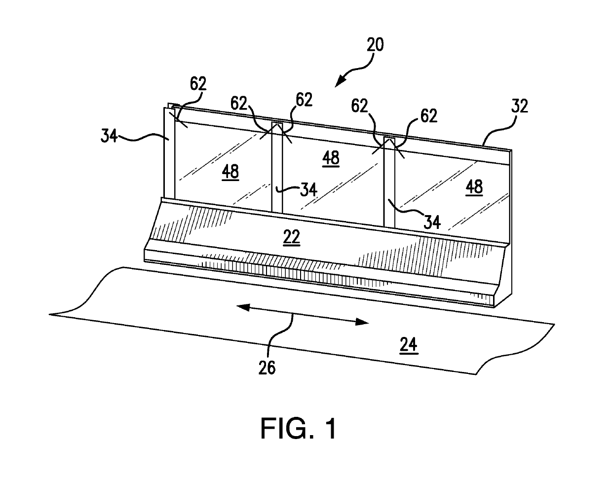
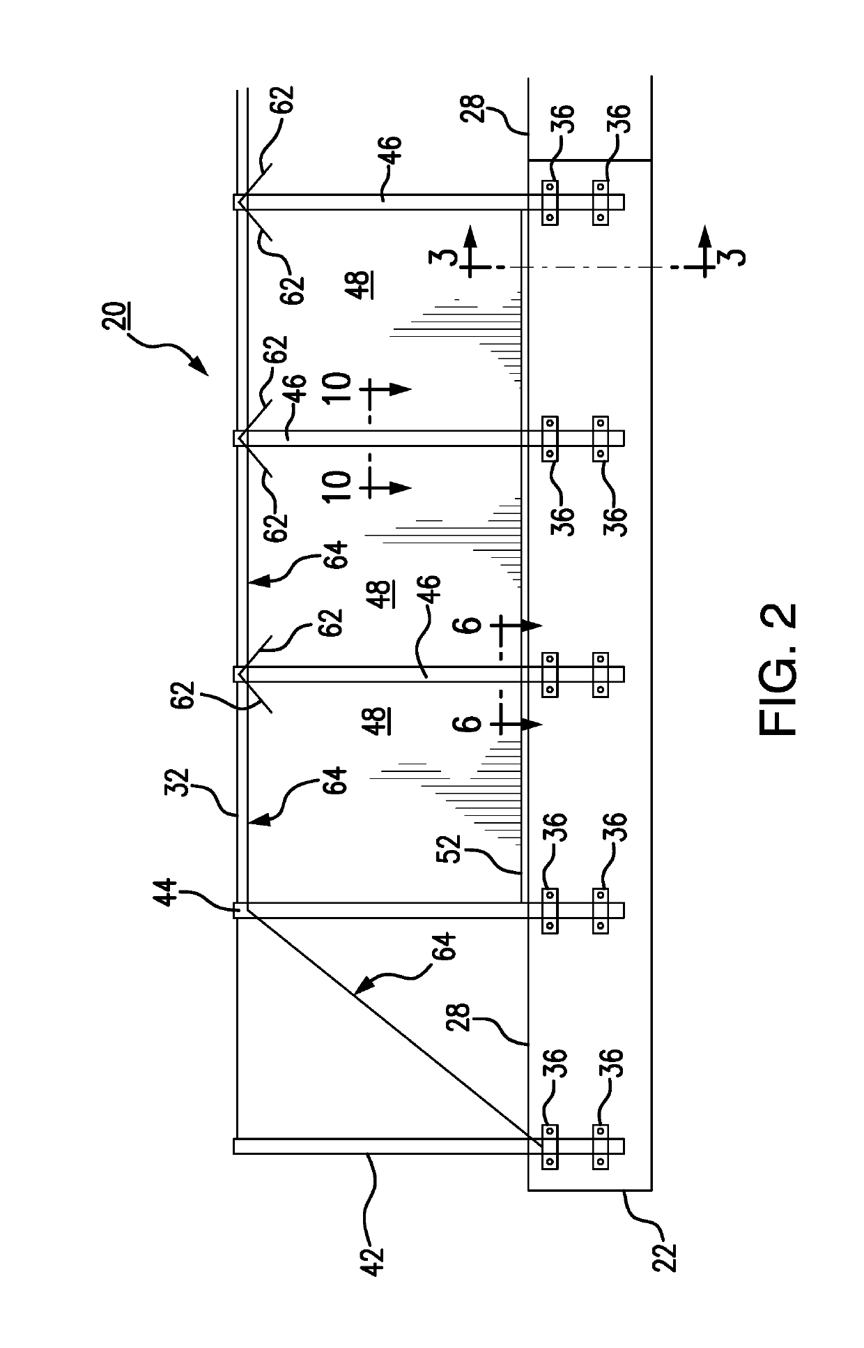
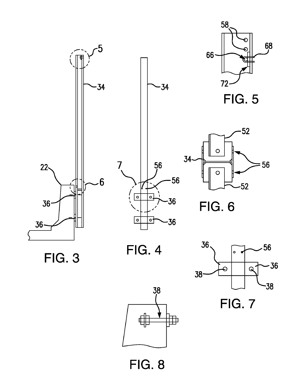
[0030]The present disclosure relates to a traffic noise barrier system that is impact resistant. The system includes a crashworthy traffic barrier that is designed to be placed adjacent a roadway and next to a flow of traffic. As part of the system, a sound wall is installed along the top of the traffic barrier. The sound wall includes a series of posts that are secured to the traffic barrier via anchor plates. Acoustic panels are secured between adjacent beams. An anchor cable extends from an anchor post, to a first post, and along a number of intermediate posts. In a preferred embodiment, the anchor cable is routed through holes in each of the posts. Each beam includes a frangible section that is designed to break upon an impact with a vehicle. When such an impact occurs, the beams and acoustic panels remain supported by the anchor cable. The various details of the present invention, and the manner in which they interrelate, are described in greater detail hereinafter.

[0031]As des...


PUM


Abstract

Disclosed is an impact resistant traffic noise barrier system. The system includes a traffic barrier that is designed to be placed adjacent a roadway and next to a flow of traffic. The design and weight of the traffic barrier permit it to withstand a variety of vehicle impacts. As part of the system, a sound wall is installed along the top of the traffic barrier. The sound wall includes a series of beams that are secured to the traffic barrier via anchor plates. Acoustic panels are secured between adjacent beams. An anchor cable extends from an anchor post, to a first post, and along a number of intermediate posts. The anchor cable is thus suspended above the traffic barrier with the anchor cable being connected to the beams. As such, the anchor cable suspends the beams in the event they become separated from the traffic barrier.

Description

CROSS REFERENCE TO RELATED APPLICATIONS[0001]This application is a continuation of, and claims priority to, co-pending Provisional Patent Application Ser. No. 62 / 613,821 filed on Jan. 5, 2018 and entitled “Impact Absorbing Traffic Noise Barrier System.” The contents of this co-pending application are expressly incorporated herein for all purposes.BACKGROUND OF THE INVENTIONField of the Invention[0002]This invention relates to a traffic noise barrier system. More particularly, the present disclosure relates to a traffic noise barrier that is designed to absorb impacts from vehicles.Description of the Background Art[0003]Noise barriers are commonly used along roadways. Noise barriers, sometimes called sound walls, are installed along roadways, such as interstate highways, county roads, streets and other thoroughfares. The noise barriers are used to acoustically isolate adjacent areas from sounds associated with automobiles, trucks, motorcycles, and other vehicular traffic. The area pr...

Claims


Application Information

Patent Timeline
Patent Type & Authority Applications(United States)
IPC IPC(8): E01F15/08E01F8/00
CPCE01F15/088E01F15/086E01F15/083E01F8/0023E01F8/0017
Inventor HUMPHRIES, ERIC CHRISTIANREX, SR., ROBERT GEORGE
Owner SUPERIOR TRANSPARENT NOISE BARRIERS LLC
Why Eureka
Try Eureka