Image forming apparatus

a technology of image forming apparatus and forming tube, which is applied in the direction of electrographic process apparatus, instruments, optics, etc., can solve the problems of low print ratio image, and inability to produce high print ratio images

Inactive Publication Date: 2019-07-25
CANON KK
View PDF1 Cites 0 Cited by
  • Summary
  • Abstract
  • Description
  • Claims
  • Application Information

AI Technical Summary

Benefits of technology

[0018]According to the present invention, the image density fluctuation which can occur during the switching from the low print ratio image to the high print ratio image can be suppressed without remarkably lowering the productivity.

Problems solved by technology

In control of maintaining the toner charge amount at the certain value, when the toner charge amount decreases, the toner application amount increases and an image density increases even when the same electrostatic image is used, and therefore, the toner charge amount is increased by decreasing a ratio of the toner as toner supply control and by increasing an opportunity of friction of the developer.

Method used


Image

  • Image forming apparatus
  • Image forming apparatus
  • Image forming apparatus

Examples


embodiment 1

(Image Forming Apparatus)

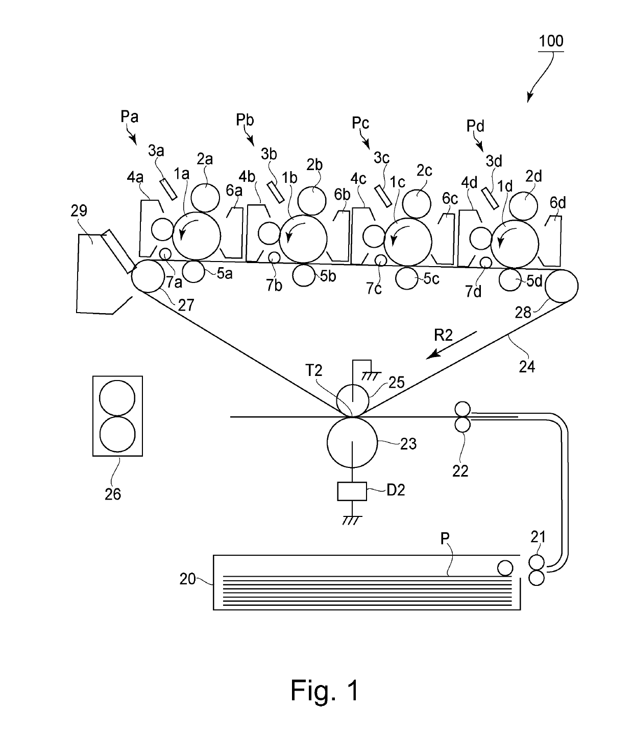
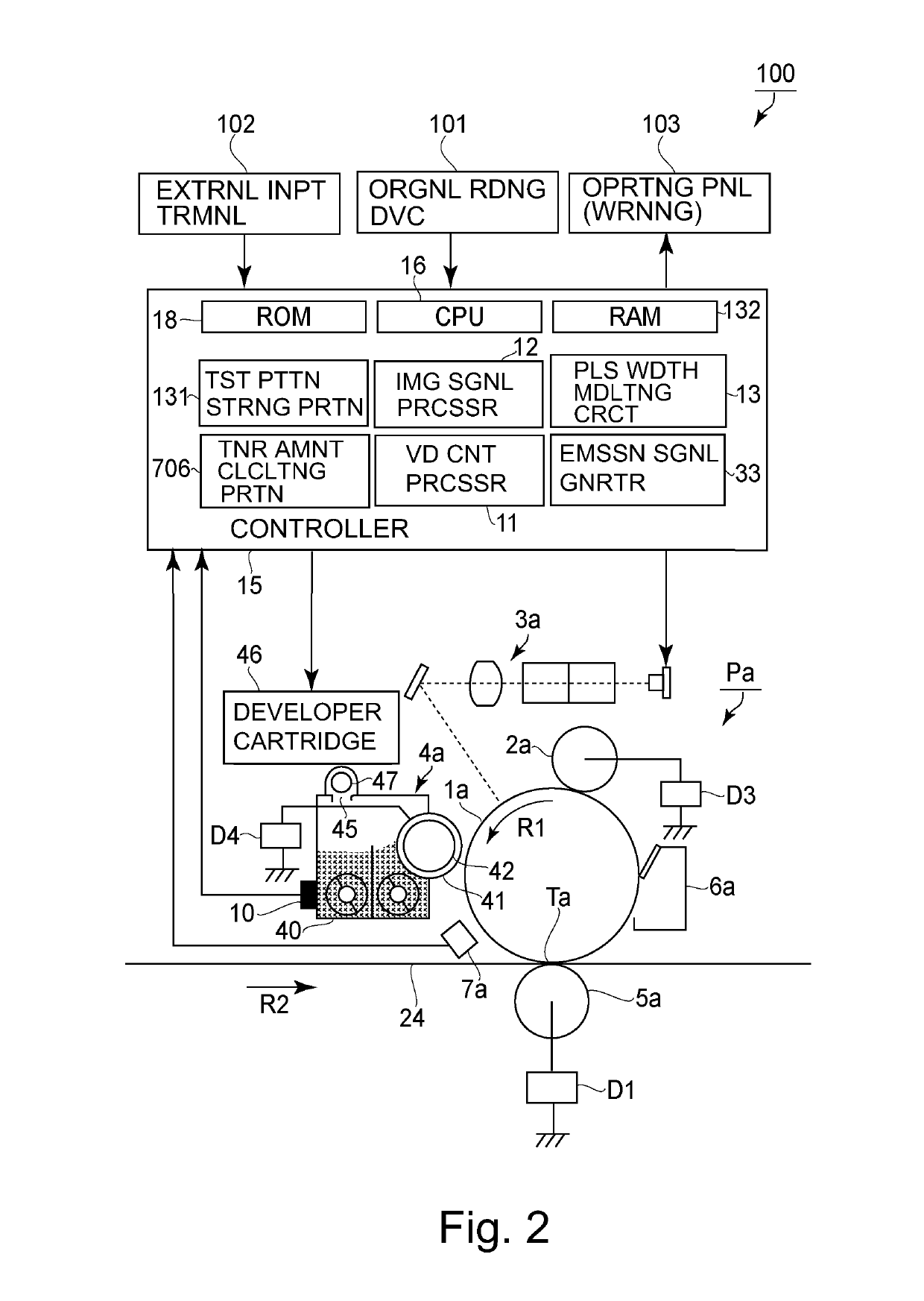
[0028]FIG. 1 is an illustration of a structure of an image forming apparatus according to this embodiment. FIG. 2 is an illustration of a structure of an image forming apparatus for yellow. As shown in FIG. 1, an image forming apparatus 100 is a full-color printer of a tandem type and an intermediary transfer type, in which image forming portions Pa, Pb, Pc and Pd for yellow, magenta, cyan and black are arranged along an intermediary transfer belt 24. At the image forming portion Pa, a yellow toner image is formed on a photosensitive drum 1a and is primary-transferred onto the intermediary transfer belt 24.

[0029]At the image forming portion Pb, a magenta toner image is formed on the photosensitive drum 1b and is primary-transferred superposedly onto the yellow toner image on the intermediary transfer belt 24. At the image forming portions Pc and Pd, a cyan toner image and a black toner image are formed and successively primary-transferred superposedly onto t...

modified embodiment

[0122]In the above-described embodiment, a preferred embodiment of the present invention was described, but the present invention is not limited thereto and is capable of being variously modified within the scope of the present invention.

modified embodiment 1

[0123]In the above-described embodiment, the correction coefficient was α0.7(ΔV<10) and α0.1(ΔV≥10), but the present invention is not limited thereto. For example, a constitution in which the target TD ratio Vtrg is changed to a value small or than the target TD ratio Vtrg before switching without changing the correction coefficient at the time of switching from the low print ratio image to the high print ratio image may also be employed. Specifically, a constitution in which the target TD ratio Vtrg is constituted as 7% which was 3% decreased from 10% before the switching may also be employed. Further, even at the time other than when the correction coefficient is made small, during the switching from the low print ratio image to the high print ratio image, control such that a ratio of the toner content control supply amount F(Td), which is a factor of the image density fluctuation, to the video count amount control supply amount F(V) is made small may only be required to be carrie...


PUM


Abstract

A developer carrying member for carrying a developer containing toner and a carrier and for developing an electrostatic image on a photosensitive member, a developer container in which the developer is electrically charged and is carried on the developer carrying member, a detecting portion for detecting a toner content, a video count means for counting and integrating the number of development dots of entirety of an image, and a supplying device for supplying a developer for supply to the developer container depending on a consumption amount of the toner are provided, and first and second toner supply amounts are acquired on the basis of outputs of the video count means and the detecting portion, and in the case where as regards a final toner supply amount determined on the basis of the first and second toner supply amounts, a fluctuation in predetermined during printing is increased from a first value to a second value, a ratio of the second toner supply amount to the first toner supply amount is decreased.

Description

TECHNICAL FIELD[0001]The present invention relates to an image forming apparatus, such as an electrophotographic copying machine or a laser beam printer, including a developing device for developing an electrostatic image formed on an image bearing member into a toner image.BACKGROUND ART[0002]An image forming apparatus in which an electrostatic image written on a photosensitive member is developed into a toner image with a developer (two-component developer) containing toner (non-magnetic) and a carrier (magnetic) has been widely used. In the developing device using the two-component developer, a toner charge amount is maintained at a certain value by adjusting a toner content occupied in the developer so that the electrostatic image formed under a predetermined charging / exposure condition is developed in a predetermined toner application amount.[0003]In control of maintaining the toner charge amount at the certain value, when the toner charge amount decreases, the toner applicatio...

Claims


Application Information

Patent Timeline
Patent Type & Authority Applications(United States)
IPC IPC(8): G03G15/08
CPCG03G15/0856G03G15/0865
Inventor AKITA, MASANORI
Owner CANON KK
Why Eureka
Try Eureka