Image forming apparatus and fixing device

a technology of fixing device and forming apparatus, which is applied in the direction of electrographic process apparatus, instruments, optics, etc., can solve the problems of reducing the fixing property at the portion where the cooling air is blown thereto, and reducing the temperature rise of the non-sheet-passing portion. , to achieve the effect of reducing productivity and suppressing occurrences

Active Publication Date: 2019-03-21
CANON KK
View PDF3 Cites 0 Cited by
  • Summary
  • Abstract
  • Description
  • Claims
  • Application Information

AI Technical Summary

Benefits of technology

[0009]A principal object of the present invention is to provide an image forming apparatus and a fixing device which are capable of suppressing occurrences of non-sheet-passing portion temperature rise and improper fixing without lowering productivity even in the case where a feeding position of a recording material is deviated with respect to a widthwise direction of the recording material.

Problems solved by technology

That is, due to a difference in heat consumption between a passing portion and a non-passing portion of the recording materials in the fixing device, a degree of temperature rise at the non-passing portion of the recording materials becomes large.
As a result a new problem such that a lowering in fixing property at a portion where the cooling air is blown thereto is caused to arise.
On the other hand, on the other side of the longitudinal end portions of the fixing member (on a side opposite from the side where the recording material is shifted with respect to the widthwise direction of the recording material), the cooling air can be blown to an entirety of the non-sheet-passing portion with respect to the longitudinal direction, so that a problem that a suppressing effect of the non-sheet-passing portion temperature rise lowers arises.
However, in this case, a problem such that productivity per unit time lowers arises.

Method used


Image

  • Image forming apparatus and fixing device
  • Image forming apparatus and fixing device
  • Image forming apparatus and fixing device

Examples


first embodiment

(Image Forming Apparatus)

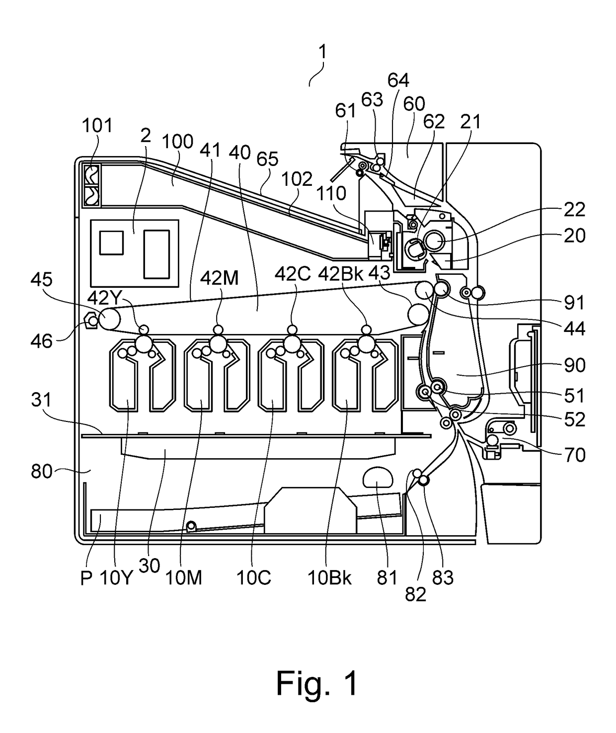
[0031]An outline of a general structure of an image forming apparatus 1 will be described with reference to FIG. 1. FIG. 1 is a longitudinal sectional view showing the general structure of a full-color laser beam printer which is an example of the image forming apparatus 1 according to this embodiment.

[0032]In the image forming apparatus 1 shown in FIG. 1, a cassette sheet feeding means 80 is provided at a lowermost portion and a manual sheet feeding means 70 is provided at a right-hand portion. The cassette sheet feeding means 80 is provided with a paper (sheet) position detecting means (described specifically later) capable of detecting both end portion positions (both end positions) of a recording material P with respect to a direction (widthwise direction) perpendicular to a feeding direction of the recording material P. Above the cassette sheet feeding means 80, a registration roller 51 and an registration opposite roller 52 which register (positionally...

second embodiment

[0070]In First Embodiment, a constitution in which the widthwise positions of the recording material P are detected by the sheet position detecting means and the shielding unit 110 is operated depending on a detection result was employed. However, the present invention is not limited thereto, and a constitution in which the shielding unit 110 is operated on the basis of values sent from the plurality of temperature detecting elements 23 and values which are stored in the image formation controller 2 in advance and which depend on the kind (size information) of the recording material P may also be employed. In the following, a constitution in which the shielding unit 110 is operated on the basis of the values sent from the plurality of the temperature detecting elements 23 and values which are stored in the image formation controller 2 in advance and which depend on the kind of the recording material P will be described.

(Shielding Unit Operation)

[0071]Next, an actual operation of the...

third embodiment

[0088]In First Embodiment, the driving motors and the pinions which correspond to those for F side and the R side are separately provided, but in this embodiment, a driving motor and a pinion are common to the F side and the R side. Incidentally, constituent elements and operations which are similar to those in First Embodiment are represented by the same reference numerals or symbols and will be omitted from description.

(Shielding Unit Structure)

[0089]Part (a) of FIG. 10 is a perspective view of a shielding unit 210 in this embodiment as seen from an upper portion of the cooling fan 101 (FIG. 1). Part (b) of FIG. 10 is a perspective view of the shielding unit 210 in this embodiment as seen from an upper portion of the fixing unit 20 (FIG. 1). The shielding unit 210 includes a shielding frame 116 which holds a driving motor 220 provided with a pinion 220a.

[0090]As shown in FIGS. 10 and 11, an F-side shielding member 211 in this embodiment is constituted by an F-side driving member ...


PUM


Abstract

An image forming apparatus includes a fixing unit including a heater, an air blowing portion, a first opening, a first shielding member changing an opening width of the first opening with respect to a longitudinal direction, a second opening, a second shielding member changing an opening width of the second opening with respect to the longitudinal direction, a detecting portion detecting a deviation amount of the recording material with respect to a widthwise direction, and a controller controlling, on the basis of an output of the detecting portion and size information of the recording material, the opening widths of the first and second openings so as to be different from each other by moving the first and second shielding members, respectively.

Description

FIELD OF THE INVENTION AND RELATED ART[0001]The present invention relates to an image forming apparatus and a fixing device which include an air blowing means for suppressing non-sheet-passing portion temperature rise.[0002]In recent years, a copying machine and a printer which use an electrophotographic process have been used not only in a large office but also by various users in a wide variety of markets such as a small office and personal use. For that reason, as regards a recording material used in the copying machine and the printer, those having not only various kinds but also various sizes have been used.[0003]Here, when small-width recording materials (small-size paper) narrower in width than maximum-size paper having a maximum width and passed through the copying machine and the printer and on which a toner image is fixable by a fixing device incorporated in the copying machine and the printer are not continuously passed through the fixing device, a so-called non-sheet-pas...

Claims


Application Information

Patent Timeline
Patent Type & Authority Applications(United States)
IPC IPC(8): G03G15/00G03G15/20
CPCG03G15/5029G03G15/2039G03G15/2017G03G15/2042G03G21/206
Inventor MITSUI, YUJI
Owner CANON KK
Why Eureka
Try Eureka