

Brushless direct current motor
a brushless, direct current technology, applied in the direction of dynamo-electric machines, magnetic circuit rotating parts, magnetic circuit shapes/forms/construction, etc., can solve the problems of vibration and noise, motor noise, etc., to reduce cogging torque and torque ripple, reduce the effect of torque rippl
Active Publication Date: 2019-08-08
HANON SYST
View PDF2 Cites 0 Cited by
- Summary
- Abstract
- Description
- Claims
- Application Information
AI Technical Summary
Benefits of technology
The present invention relates to a BLDC motor that can reduce cogging torque and torque ripple by reducing the magneto-resistance between the stator and the rotor. This can lead to a more sinusoidal counter electromotive force waveform and reduce noise and vibration of the motor.
Problems solved by technology
Method used
View moreImage
Smart ImageViewing Examples

Examples
Embodiment Construction
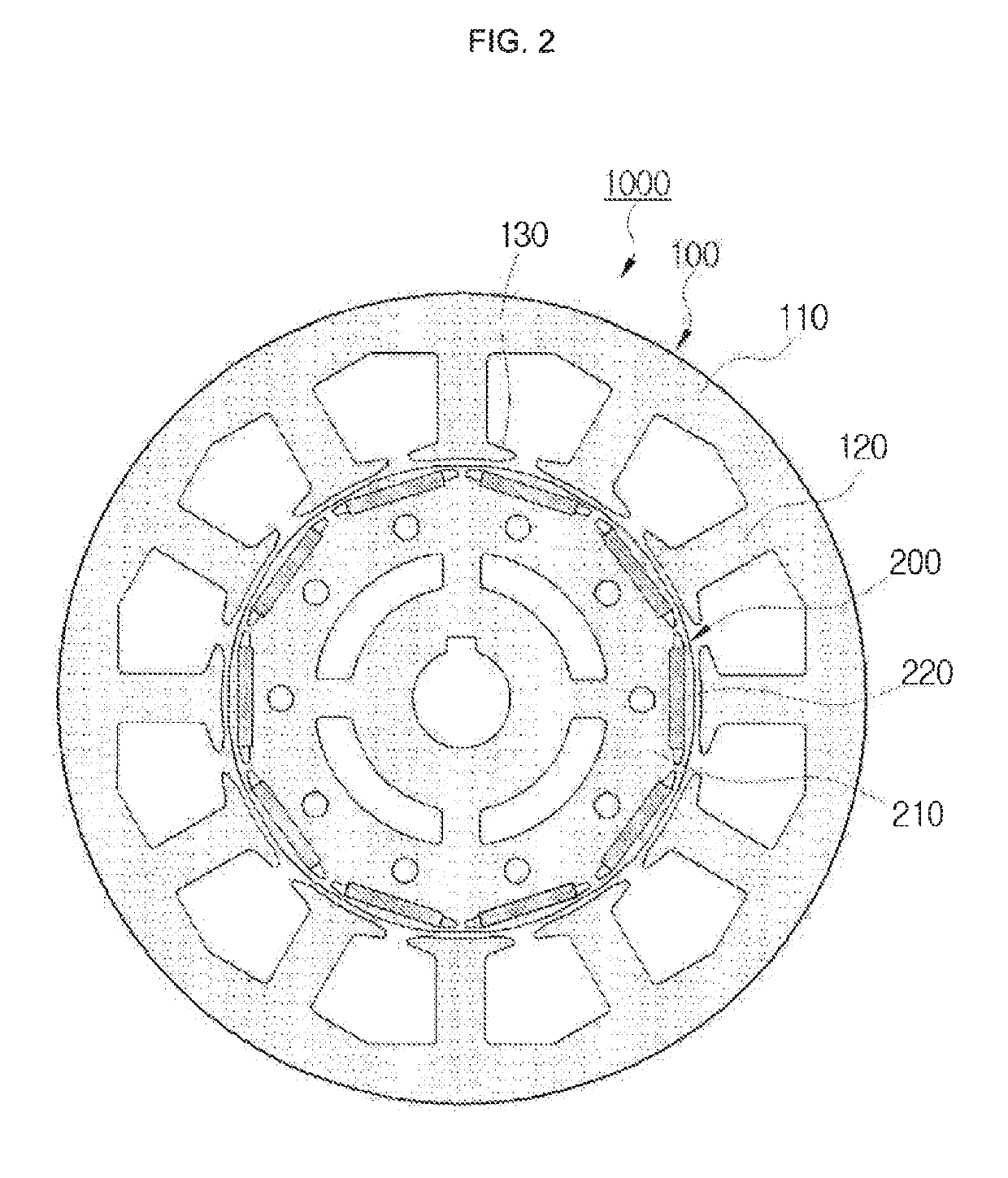
[0053]1000: BLDG motor
[0054]100: Stator
[0055]110: Core
[0056]120: Teeth
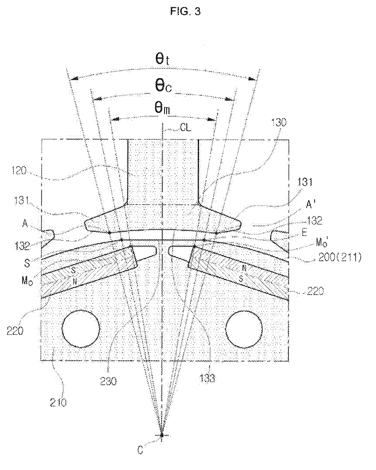
[0057]130: Pole shoe
[0058]131: End part
[0059]132: Straight portion
[0060]133: Arch portion
[0061]200: Rotor
[0062]210: Core
[0063]211: Outer circumferential surface
[0064]220: Permanent magnet
[0065]230: Straight portion
[0066]A, A′: Start point of straight portion of pole shoe of stator
[0067]Mo, Mo′: Outer side end of permanent magnet
[0068]S: Start point of straight portion of rotor
[0069]E: End point of straight portion of rotor
[0070]C: Rotation center of rotor
[0071]CL: Central line of pole shoe
Login to View More PUM
 Abstract
Disclosed is a BLDC motor, including: a stator which is provided with a plurality of teeth extending toward an inner side of a core and pole shoes each extending to be formed at radial inner end parts of the teeth; and rotors which are disposed at an inner side of the stator surrounded by the pole shoes while being spaced apart from the stator and have a plurality of permanent magnets coupled to cores thereof. Inner circumferential surfaces of the circumferential end parts of the pole shoe may be formed so that a distance of the inner circumferential surfaces of the circumferential end parts of the pole shoe from the outer circumferential surface of the rotor increases as the inner circumferential surfaces of the circumferential both end parts of the pole shoe is far away circumferentially from a central line CL of the pole shoe.
Description
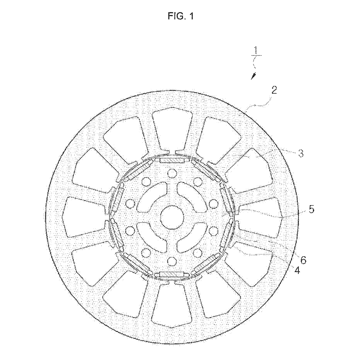
TECHNICAL FIELD[0001]The present invention relates to a BLDC motor, and more particularly, to a BLDC motor capable of reducing a cogging torque and a torque ripple in an inner-rotor type BLDC motor.BACKGROUND ART[0002]A brushless direct current (BLDC) motor may prevent friction and wear which are disadvantages of the existing DC motor and have relatively high efficiency. Therefore, recently, hybrid cars tend to adopt the BLDC motor as a motor for rotating a cooling fan.[0003]The BLDG motor is a motor that does not have a brush and a commutator necessary for a DC motor but has an electronic commutation mechanism installed therein. Among the BLDC motors, an inner-rotor type BLDG motor includes a rotor and a stator, in which the rotor whose center is provided with a permanent magnet rotates and the stator whose circumference is wound with a drive coil is fixed. That is, the stator whose outer side is wound with the drive coil is fixed and the rotor whose inner side is provided with the...
Claims
Login to View More Application Information
Patent Timeline
 Patent Type & AuthorityApplications(United States)
IPC IPC(8): H02K1/27
CPCH02K1/276H02K29/03H02K1/146H02K1/2766H02K1/12H02K1/274H02K29/00
InventorSHIN, HYEON JAEIM, HO BINJUNG, KYUNG HUNCHO, SEONG KOOKJIN, JAE KYOUNG
OwnerHANON SYST