Compact test range for active optical target detectors

a target detector and compact technology, applied in the direction of instruments, optical elements, measurement devices, etc., can solve the problems of large space requirements and high cost, and achieve the effect of reducing linear distance, reducing linear distance, and reducing linear distan

Active Publication Date: 2019-08-15
RAYTHEON CO
View PDF7 Cites 4 Cited by
  • Summary
  • Abstract
  • Description
  • Claims
  • Application Information

AI Technical Summary

Benefits of technology

[0003]In a first embodiment, a test system for an electro-optic range-finding device is positioned proximate to a laser aperture and a detector aperture for the range-finding device to be tested. One or more fiber bundles each has a length selected to correspond to predetermined time-of-flight for light pulses to travel from the laser aperture to the detector aperture. An input end of each of the one or more fiber bundles is positioned proximate to the laser aperture to receive a portion of light emitted through the laser aperture. An output end of each of the one or more fiber bundles is positioned proximate to the detector aperture to emit light from the respective fiber bundle through the detector aperture. A fiber attenuator is connected along each fiber of the one or more fiber bundles to attenuate an amplitude of light propagating through the respective fiber by an amount corresponding to a target of known reflectance and distance. The one or more fiber bundles are each coiled to reduce a linear distance over which the one or more fiber bundles extend. The one or more fiber bundles may each comprise a plurality of fibers. The one or more fiber bundles may comprise a first fiber bundle having a first length corresponding to a first time-of-flight for light pulses and a second fiber bundle having a second length corresponding to a second time-of-flight for light pulses. The fiber attenuators connected along each fiber of the first fiber bundle may each attenuate an amplitude of light pulses within a respective fiber by at least an amount corresponding to the first time-of-flight for light pulses propagating a first distance in open air, and the fiber attenuators connected along each fiber of the second fiber bundle may each attenuate an amplitude of light pulses within a respective fiber by at least an amount corresponding to the second time-of-flight for light pulses for light pulses propagating a second distance in open air. The one or more fiber bundles may comprise a plurality of fiber bundles, in which case the input ends of the fiber bundles may be distributed at spaced-apart points along a cross-section of the light emitted through the laser aperture. When the one or more fiber bundles comprises a plurality of fibers, a positional mask may be disposed between at least one of the input ends and the output ends of the fibers, the positional mask including an aperture that one of allows light from the laser aperture to enter one of the fibers while blocking light from the laser aperture from entering remaining ones of the fibers, or allows light from one of the fibers to enter the detector aperture while blocking light from remaining ones of the fibers from entering the detector aperture. When present, the positional mask may multiplex one of light from the laser aperture to the fibers or light from the fibers to the detector aperture.
[0004]In a second embodiment, during testing, an electro-optic range-finding device is positioned proximate to a testing system and operated to emit light pulses through a laser aperture and receive light through a detector aperture. One or more fiber bundles are positioned to carry a portion of light in the light pulses from the laser aperture to the detector aperture, each of the one or more fiber bundles each having a length selected to correspond to a predetermined time-of-flight for the light pulses to travel from the laser aperture to the detector aperture. An input end of each of the one or more fiber bundles is positioned proximate to the laser aperture to receive a portion of light emitted through the laser aperture, and an output end of each of the one or more fiber bundles is positioned proximate to the detector aperture to emit light from the respective fiber bundle through the detector aperture. A fiber attenuator is connected along each fiber of the one or more fiber bundles to attenuate an amplitude of light propagating through the respective fiber by an amount corresponding to a target of known reflectance and distance. The one or more fiber bundles are coiled to reduce a linear distance over which the one or more fiber bundles extend. The one or more fiber bundles may each comprise a plurality of fibers. The one or more fiber bundles may comprise a first fiber bundle having a first length corresponding to a first time-of-flight for light pulses and a second fiber bundle having a second length corresponding to a second time-of-flight for light pulses. The fiber attenuators connected along each fiber of the first fiber bundle may each attenuate an amplitude of light pulses within a respective fiber by at least an amount corresponding to the first time-of-flight for light pulses propagating a first distance in open air and the fiber attenuators connected along each fiber of the second fiber bundle each attenuate an amplitude of light pulses within a respective fiber by at least an amount corresponding to the second time-of-flight for light pulses for light pulses propagating a second distance in open air. When the one or more fiber bundles comprise a plurality of fiber bundles, the input ends of the fiber bundles may be distributed at spaced-apart points along a cross-section of the light emitted through the laser aperture. When the one or more fiber bundles comprises a plurality of fibers, a positional mask may be disposed between at least one of the input ends and the output ends of the fibers, the positional mask including an aperture that one of allows light from the laser aperture to enter one of the fibers while blocking light from the laser aperture from entering remaining ones of the fibers, or allows light from one of the fibers to enter the detector aperture while blocking light from remaining ones of the fibers from entering the detector aperture. When present, the positional mask may multiplex one of light from the laser aperture to the fibers or light from the fibers to the detector aperture.
[0005]In a third embodiment, a test / calibration system includes: a first fiber bundle having a first length selected such that time-of-flight for light pulses to travel from an input end of the first fiber bundle to an output end of the first fiber bundle corresponds to time-of-flight for the light pulses to travel a first distance in open air; a first fiber attenuator connected along each fiber of the first fiber bundle to attenuate an amplitude of light propagating through the respective fiber by an amount corresponding to reflection of light traveling in open air from a target of known reflectance at the first distance; a second fiber bundle having a second length selected such that time-of-flight for light pulses to travel from an input end of the second fiber bundle to an output end of the second fiber bundle corresponds to time-of-flight for the light pulses to travel a second distance in open air; and a second fiber attenuator connected along each fiber of the second fiber bundle to attenuate an amplitude of light propagating through the respective fiber by an amount corresponding to reflection of light traveling in open air from the target of known reflectance at the second distance, where the first and second fiber bundles are coiled to reduce a linear distance over which the first and second fiber bundles extend. The first and second fiber bundles may each comprise a plurality of fibers. When the first fiber bundle is one of a plurality of fiber bundles having the first length, the input ends of the fiber bundles having the first length may be distributed at spaced-apart points. The test / calibration system may also include an opaque shroud surrounding one of input ends of fibers within the first and second fiber bundles or output ends of fibers within the first and second fiber bundles. The test / calibration system may further include an electro-optic range-finding device having a laser aperture and a detector aperture, wherein an input end of each of the first and second fiber bundles is positioned proximate to the laser aperture to receive a portion of light emitted through the laser aperture, and wherein an output end of each of the first and second fiber bundles is positioned proximate to the detector aperture to emit light from the respective fiber bundle through the detector aperture. When the test / calibration system includes an electro-optic range-finding device, that device may include a light transmitter assembly configured to emit the light pulses through the laser aperture, a light receiver assembly configured to receive light through the detector aperture, and a processor configured to calibrate the electro-optic range-finding device based on light received through the detector aperture from the first and second fiber bundles based on light emitted through the laser aperture into the first and second fiber bundles.
[0006]Although specific advantages have been enumerated above, various embodiments may include some, none, or all of the enumerated advantages. Additionally, other technical advantages may become readily apparent to one of ordinary skill in the art after review of the following figures and description.

Problems solved by technology

However, the space required can be sizable and costly, and accuracy may be influenced by spurious reflectance or emissions from background objects.

Method used


Image

  • Compact test range for active optical target detectors
  • Compact test range for active optical target detectors
  • Compact test range for active optical target detectors

Examples


Embodiment Construction

[0013]It should be understood at the outset that, although exemplary embodiments are illustrated in the figures and described below, the principles of the present disclosure may be implemented using any number of techniques, whether currently known or not. The present disclosure should in no way be limited to the exemplary implementations and techniques illustrated in the drawings and described below. Additionally, unless otherwise specifically noted, articles depicted in the drawings are not necessarily drawn to scale.

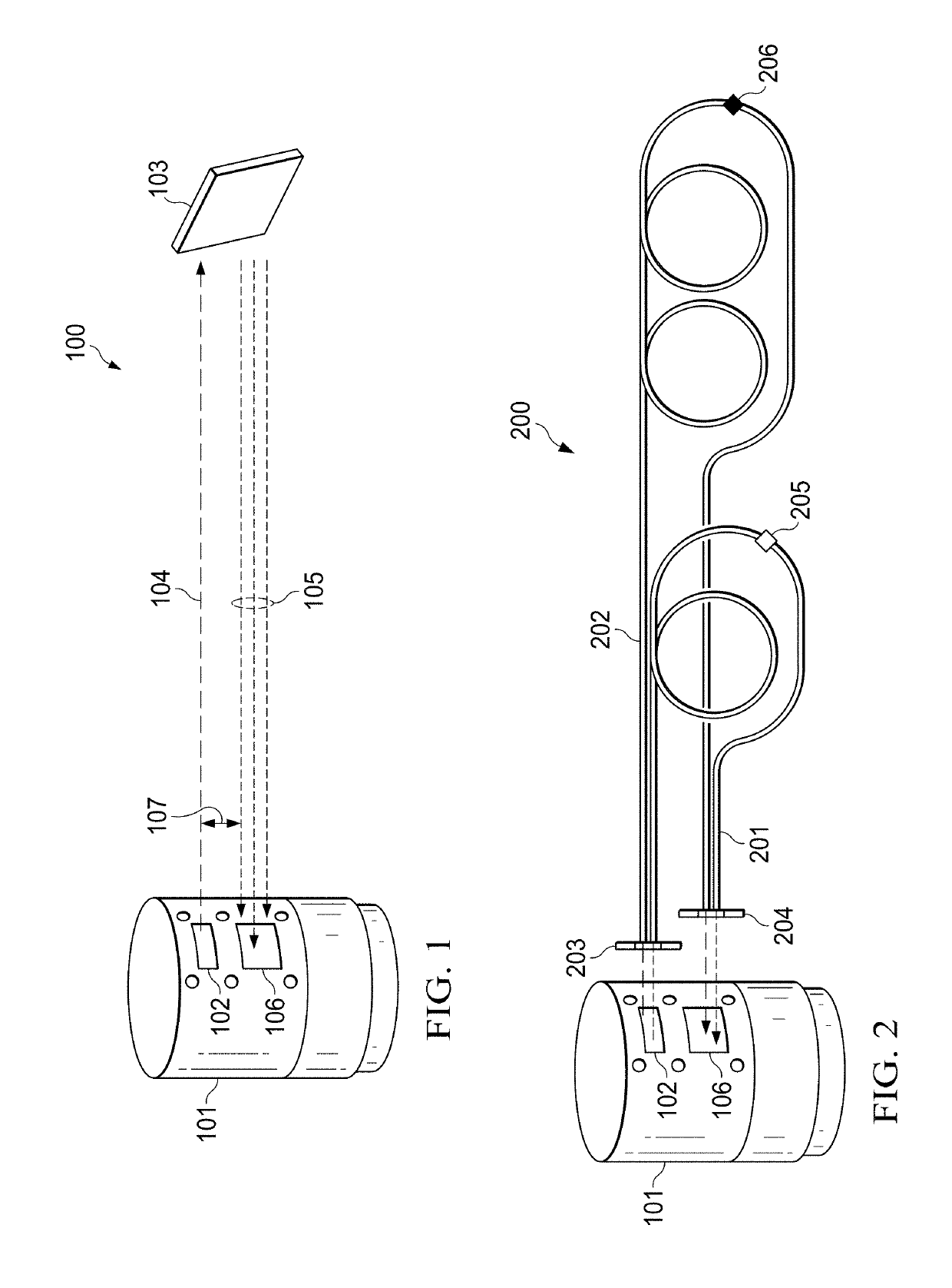
[0014]Electro-optic (EO) devices such as active optical target detectors (AOTDs) may be employed to detect objects over a range of distances. For example, a missile equipped with “near miss” detection, in order to detonate munitions when the target is within a predetermined range despite the lack of a direct hit, may detect decreasing and then increasing distance to the target as well as whether the current range to the target is less than a maximum distance at which ...


PUM

PropertyMeasurementUnit
distancesaaaaaaaaaa
distanceaaaaaaaaaa
lengthaaaaaaaaaa

Abstract

For test/calibration of an electro-optic range-finding device, one or more fiber bundles each are selected to have a length corresponding to predetermined time-of-flight for light pulses. An input end is positioned proximate to the laser aperture of the range-finding device to receive a portion of light emitted through the laser aperture, and the output end is positioned to emit light from the respective fiber bundle through the detector aperture of the range-finding device. A fiber attenuator is connected along each fiber of the one or more fiber bundles to attenuate an amplitude of light propagating through the respective fiber by an amount corresponding to a target of known reflectance and distance. The one or more fiber bundles are each coiled to reduce a linear distance over which the one or more fiber bundles extend. The one or more fiber bundles may each comprise a plurality of fibers.

Description

TECHNICAL FIELD[0001]The present disclosure is directed in general to test or calibration systems for optical target detectors and more particularly to reducing the space required for and the accuracy of such test or calibration systems.BACKGROUND OF THE DISCLOSURE[0002]Optical target detectors may be tested and / or calibrated using a flat target of known reflectance at several distances. However, the space required can be sizable and costly, and accuracy may be influenced by spurious reflectance or emissions from background objects.SUMMARY OF THE DISCLOSURE[0003]In a first embodiment, a test system for an electro-optic range-finding device is positioned proximate to a laser aperture and a detector aperture for the range-finding device to be tested. One or more fiber bundles each has a length selected to correspond to predetermined time-of-flight for light pulses to travel from the laser aperture to the detector aperture. An input end of each of the one or more fiber bundles is posit...

Claims


Application Information

Patent Timeline
Patent Type & Authority Applications(United States)
IPC IPC(8): G01S7/497G02B6/42G02F1/01G01S17/10
CPCG01S7/497G02B6/4298G02F1/0115G01S17/10G02B6/4206G01S7/4818G01S7/4972
Inventor CRAWFORD, JOHNMILLARD, JOHN
Owner RAYTHEON CO
Why Eureka
Try Eureka