Matrix for imprinting a raised pattern on a coating

Inactive Publication Date: 2019-08-22
SAINT GOBAIN WEBER GMBH
View PDF2 Cites 0 Cited by
  • Summary
  • Abstract
  • Description
  • Claims
  • Application Information

AI Technical Summary

Benefits of technology

The patent describes a method to create a positive texture on a coating by using a mat with a raised or reduced surface. This technique helps to make the texture easier to read and prevents air bubbles between the mat and coating. The mat can be integrated into a production process of cement or plaster-based materials, and can be used to texture prefabricated elements used in façades, floors, or internal structures.

Problems solved by technology

The method described in the above document is difficult to use, however, since it necessitates correct positioning of the mat by means of positioning markers at the time of treating two adjacent zones of the substrate, in order to prevent the joins between said zones being visible.

Method used


Image

  • Matrix for imprinting a raised pattern on a coating
  • Matrix for imprinting a raised pattern on a coating
  • Matrix for imprinting a raised pattern on a coating

Examples


first embodiment

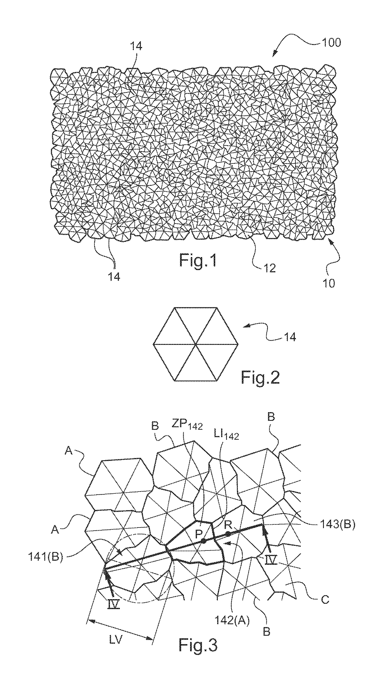
[0063]FIG. 1 shows a mat 100 intended for imprinting a texture on a coating, notably a façade of a building.

[0064]The mat 100 includes a surface 10 with a so-called random texture 12 to be imprinted, formed by a set of interpenetrating unitary elements 14.

[0065]The textured surface typically has a total surface area between 0.1 and 1.5 m2 inclusive.

[0066]In the example, the texture is a so-called “positive” texture, formed by the random juxtaposition of unitary elements 14 over a so-called base surface SB of the mat (shown by way of illustration in FIG. 4).

[0067]In this instance, the unitary elements 14 of the texture 12 from FIG. 1 are pyramids of the type shown from above in FIG. 2, with bases in the shape of a regular hexagon.

[0068]FIG. 2 shows a pyramid of this kind from above, and FIG. 3 shows in more detail the texture of the mat and the interpenetration of the unitary elements.

[0069]For a clearer understanding, the profile of the texture of the mat in section taken along the...

second embodiment

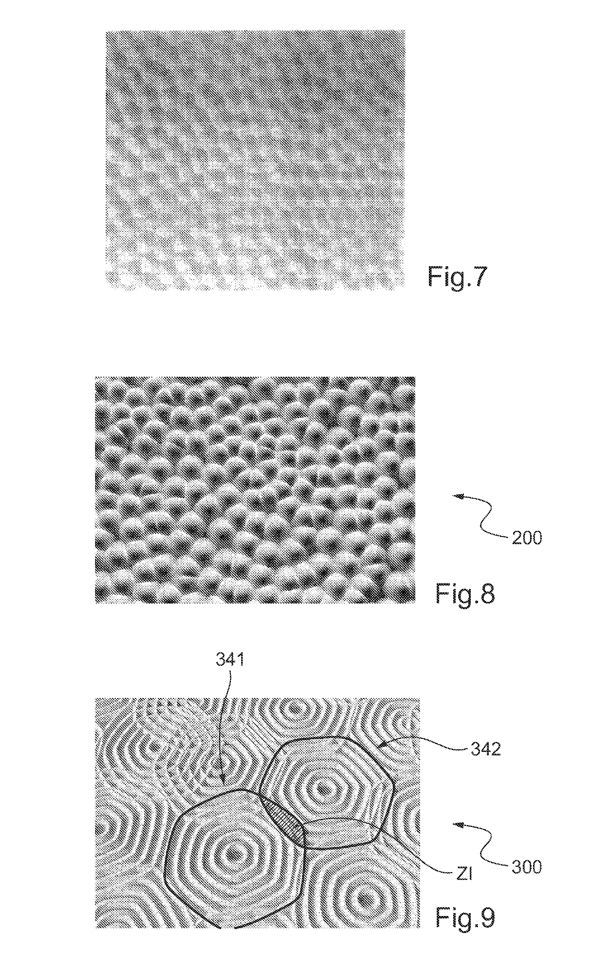
[0091]FIG. 8 shows a mat 200 in accordance with a second embodiment, comprising a texture surface formed by a set of rounded protuberances with the same shape and the same dimensions, interpenetrating in a random manner and invisibly.

[0092]FIGS. 9 to 11 show texture surfaces of matrices according to other embodiments of the invention.

[0093]In contrast to the first two embodiments described above, the textures shown here are textures with visible interpenetration. In the interpenetration zones, it is possible to distinguish the parts of one and the other of the interpenetrating unitary elements.

[0094]In the FIG. 9 embodiment, for example, the mat 300 has a texture formed by a set of interpenetrating unitary elements, each unitary element being constituted of a plurality of (here six) concentric ribs. Here the unitary element is formed by a circular central rib and five hexagonal ribs with curved sides.

[0095]There have been shown in bold in the figure the peripheral edges of two inter...


PUM

PropertyMeasurementUnit
Widthaaaaaaaaaa
Widthaaaaaaaaaa
Heightaaaaaaaaaa

Abstract

A mat for imprinting a texture on a coating, notably a coating applied to a wall, a floor or a ceiling, includes a surface with a random texture to be imprinted, formed by a set of interpenetrating unitary elements.

Description

TECHNICAL FIELD[0001]The present invention concerns the imprinting of a texture on a coating, also known as texturing a coating, notably a coating applied to a wall, a floor or a ceiling or to part of a prefabricated element used in the construction of a wall, a floor or a ceiling.[0002]The present invention more particularly concerns a mat suitable for this kind of imprinting.BACKGROUND OF THE INVENTION[0003]It is known to deposit a coating layer on a wall or a floor to be coated. Applied to a façade of a building, the coating generally has a function of decoration and of impermeability. Applied to an inside wall, its function is mainly decorative. There exist different types of coating as a function of the binder that it contains. A coating can contain an organic binder, for example an acrylic resin (organic coating) or a mineral binder for example cement, plaster and / or lime (mineral coating). The choice of the type of coating depends on the intended application.[0004]To enhance ...

Claims


Application Information

Patent Timeline
IPC IPC(8): B44C1/24E04F21/04
CPCB44C1/24E04F21/04B44B11/04B44B5/026E01C19/43B44B5/0052B29C59/022
Inventor DEVORET, ANNECLAUDE, CAMILLEBALESTE, STÉPHANIEGIRET, ANTOINE
Owner SAINT GOBAIN WEBER GMBH
Why Eureka
Try Eureka