Anchor for hardenable compound

a compound and hardening technology, applied in the direction of fastening means, dowels, mechanical devices, etc., to achieve the effect of facilitating the passage of resin and preventing air pockets in the resin

Active Publication Date: 2020-03-17
ILLINOIS TOOL WORKS INC
View PDF26 Cites 0 Cited by
  • Summary
  • Abstract
  • Description
  • Claims
  • Application Information

AI Technical Summary

Benefits of technology

[0016]The member is therefore similar to a piston able to move longitudinally inside the sheath. The screw is used to move the member. When screwing in the screw, the member is moved away from the second end of the sheath and therefore toward the first end of the sheath. The sheath is not necessarily intended to be deformed upon movement of the member and is therefore able to retain its initial tubular shape. The movement of the member can make it possible to drive a polymerizable resin when the anchor is intended to be used as a chemical anchor. The driving of the resin in the sheath makes it possible to join it up and to compact it, thereby preventing air pockets in the resin. It can moreover make it possible to facilitate the passage of the resin out of the sheath to come into contact with said support material and thereby to favor the chemical fastening of the anchor. It is therefore clear that the movement of the member can drive longitudinal and / or radial movement of the resin relative to the longitudinal axis of the anchor and the sheath.

Problems solved by technology

A disadvantage of these chemical anchors is that it is necessary to wait for the mixture of components to be polymerized and to harden before being able to apply a load to the stud or the screw.

Method used


Image

  • Anchor for hardenable compound
  • Anchor for hardenable compound
  • Anchor for hardenable compound

Examples


Embodiment Construction

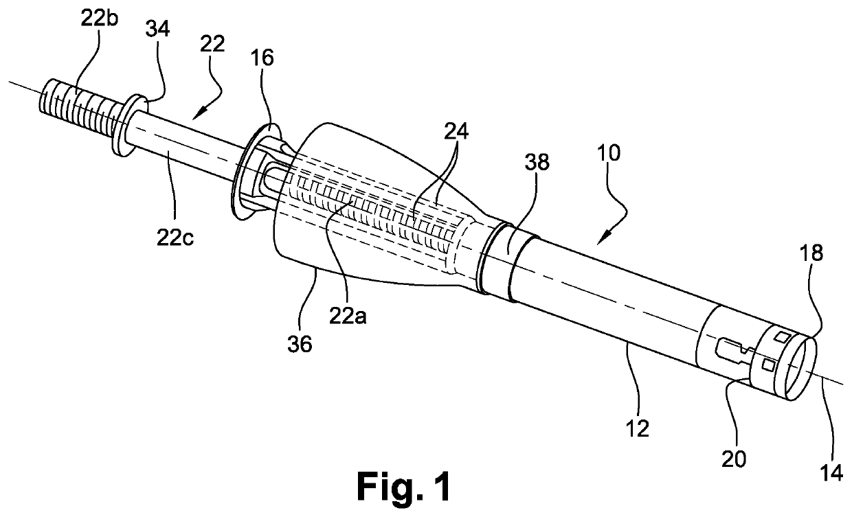
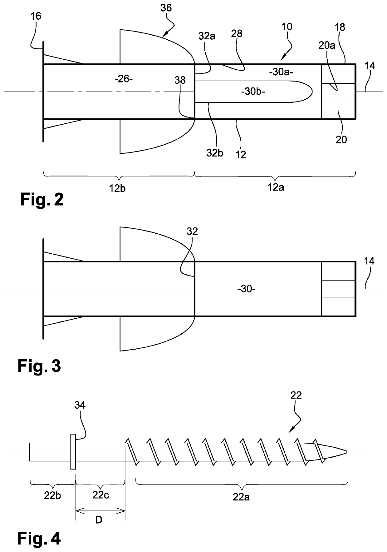
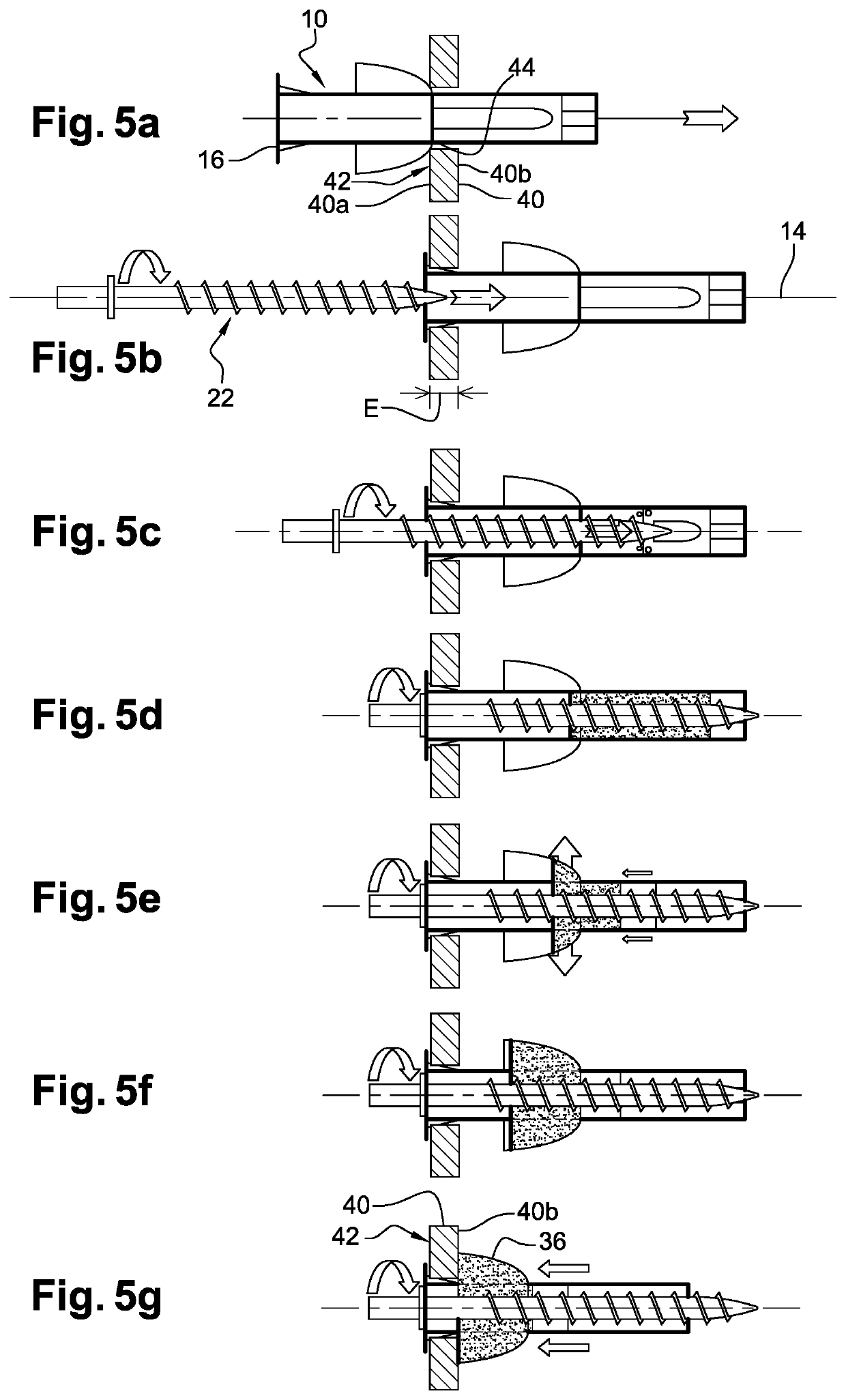
[0052]FIGS. 1, 2 and 4 represent a fastening kit in accordance with a first embodiment of the present disclosure that includes an anchor 10, here a chemical anchor, this anchor 10 serving notably for fastening a component to a support material which may be hollow or solid, as will be described in detail with reference to FIGS. 5a to 5g and 6a to 6f, respectively.

[0053]The anchor 10 includes a tubular sheath 12, here made of plastic material, having a longitudinal axis 14. The sheath 12 is made from a thermoplastic material, for example, such as polyamide (for example PA6).

[0054]The sheath 12 extends between a first end including a bearing mechanism 16 that is formed here by an annular bearing flange, and a second end 18 opposite the flange 16.

[0055]A member and in this illustrated example embodiment a piston member 20 is housed in the sheath 12 at the level of its second end 18. In the example represented, this piston member 20 comprises an internal screwthread 20a that may comprise...


PUM


Abstract

Anchor for fastening a component to a hollow or solid support material, said anchor comprising a sheath of elongate shape that is intended to be introduced into a hole in said support material, said anchor also comprising a bearing mechanism for bearing against an external face of said support material, situated at a first longitudinal end of said sheath, and a piston member situated at a second, opposite longitudinal end of said sheath and configured to engage with a screw intended to be introduced into said sheath, characterized in that said piston member is configured to be moved longitudinally inside said sheath by said screw.

Description

PRIORITY CLAIM[0001]This patent application is a national stage entry of PCT Application No. PCT / US2016 / 049675, which was filed on Aug. 31, 2016, which claims priority to and the benefit of French Patent Application No. 1559172, which was filed on Sep. 29, 2015, the entire contents of which are incorporated herein by reference.TECHNICAL FIELD[0002]The present disclosure concerns an anchor, in particular a chemical anchor, notably for fastening a component to a support material, and a fastening kit including a screw and such an anchor.PRIOR ART[0003]The prior art notably includes the documents FR-A1-2 896 283, FR-A1-2 903 784, FR-A1-2 917 792 and FR-A1-3 017 910.[0004]A chemical anchor is an anchor that is fixed to a support material with the aid of a heat-setting resin and a hardener or activator for polymerizing the resin.[0005]At present, there exist chemical anchors for solid materials and chemical anchors for hollow materials.[0006]In the case of a solid material, a hole may be ...

Claims


Application Information

Patent Timeline
Patent Type & Authority Patents(United States)
IPC IPC(8): F16B13/08F16B13/14
CPCF16B13/141F16B13/0833F16B13/08
Inventor COUVREUR, JÉRÔMESIMONIN, JEAN-LUCMARASCO, JEAN-PAUL
Owner ILLINOIS TOOL WORKS INC
Why Eureka
Try Eureka