
Sealing device

a sealing device and sealing technology, applied in the direction of engine seals, mechanical devices, engine components, etc., can solve the problems of abrasion resistance, abrasion resistance, abrasion resistance and sealability,

Inactive Publication Date: 2019-08-29
SANWA KOKI KK
View PDF2 Cites 0 Cited by
  • Summary
  • Abstract
  • Description
  • Claims
  • Application Information

AI Technical Summary

Benefits of technology

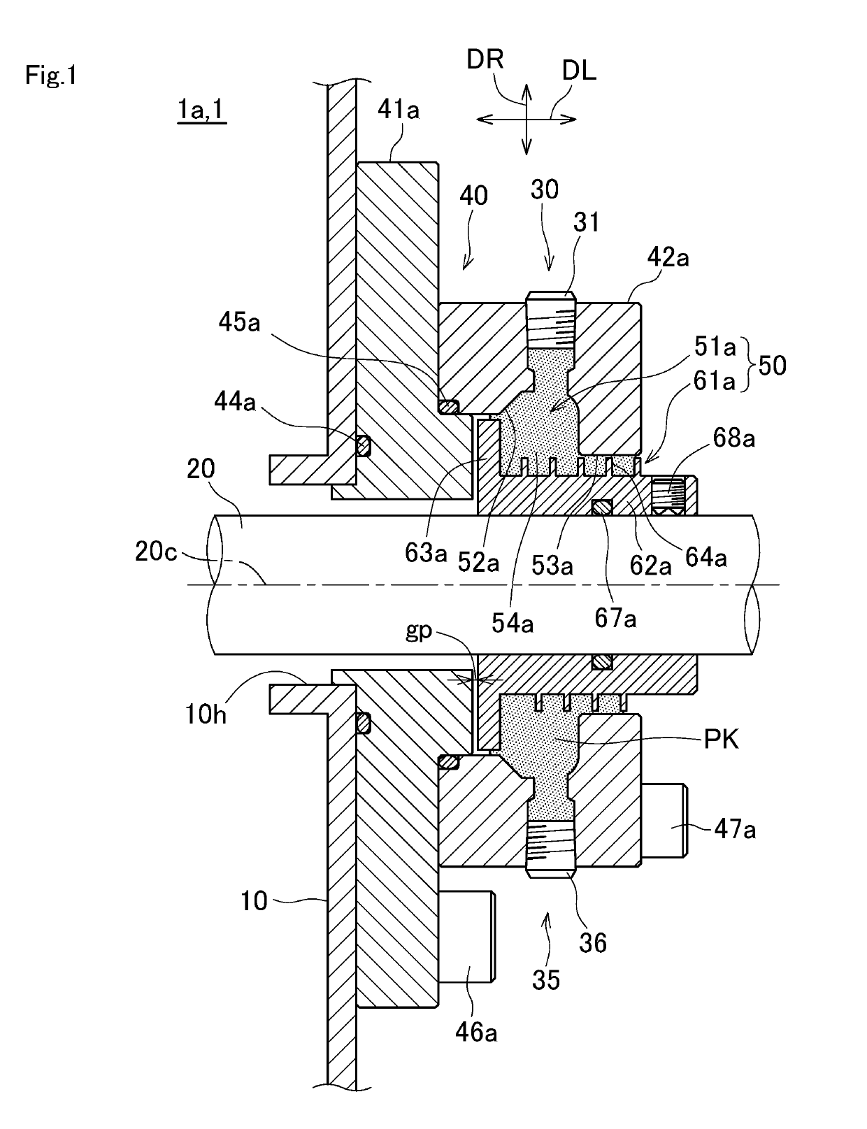
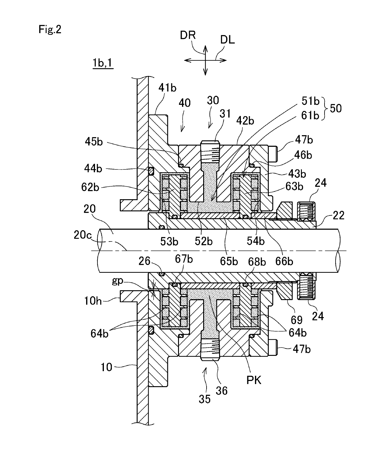
The present invention is a sealing device that improves sealability and durability compared to existing methods and apparatuses. The device includes a housing fixed to a container, a filler filled between the housing and a rotating shaft, a holding mechanism part fixed to the rotating shaft and positioned between the rotating shaft and the housing to hold the filler, and a regulation part positioned in the holding mechanism part and suppressing leakage of the filler. The holding mechanism part stores the filler and eliminates friction, enhancing sealability and durability. The device seals the space between the container and the rotating shaft with the filler, making it easy to enhance sealability.

Problems solved by technology

In the conventional mechanical seal, there has been an issue in an abrasion resistance due to the friction between a rotary ring, which rotates with a rotating shaft, and a fixing ring.
Further, in the conventional sealing device applying the gland packing, there has been an issue in an abrasion resistance due to the pressurized state between the gland packing and the shaft.
That is, in the conventional sealing device, a sliding part exists, so that there have been issues in the abrasion resistance and the sealability due to the abrasion resistance.

Method used


Image

  • Sealing device
  • Sealing device

Examples


embodiment 3

[0089]Regarding the filler PK and the regulation part gp in embodiments 1 and 2, it will be further described as embodiment 3.

[0090]The required conditions of the filler PK in embodiments 1 and 2 are to secure the filling performance when the filler PK fills from outside and to secure the sealability after filling with the filler PK in the holding mechanism part 50 positioned between the rotating shaft 20 and the housing 40.

[0091]That is, in order to fill with the filler PK in the holding mechanism part 50, it requires the liquidity and the lubricity of the filler PK filling the holding mechanism part 50, and further, it requires the sealability to prevent the regulation part gp positioned between the rotating shaft 20 side and the housing (container 10) side in the shaft direction DL of the holding mechanism part 50 from leaking. The sealability of the filler PK is defined by, mainly, viscosity. Accordingly, the required viscosity of the filler PK is defined by the physical propert...


PUM


Abstract

A sealing device seals between a rotating shaft inserted into a container and the container. The sealing device includes a housing positioned around the rotating shaft and fixed to the container, a filler filled between the housing and the rotating shaft, and a holding mechanism part securing the filler positioned between the housing and the rotating shaft. The holding mechanism part includes a storing chamber in which the filler is stored in a housing side with respect to the rotating shaft, and a driving part which projects to the storing chamber fixed to the rotating shaft and is driven to flow the filler.

Description

CROSS-REFERENCE TO RELATED APPLICATIONS[0001]The present application claims priority under 35 U.S.C. 119 to Japanese Patent Application No. 2018-34851, filed on Feb. 28, 2018. The contents of this application are incorporated herein by reference in their entirety.BACKGROUND OF THE INVENTIONField of the Invention[0002]The present invention relates to a sealing device which easily enhances sealability and durability between a rotating shaft inserted into a container and the container.Description of the Related Art[0003]As a conventional sealing device, one employing a mechanical seal (see e.g., Japanese Patent Application Publication No. 2013-177914), or one employing a gland packing (see e.g., Japanese Patent Application Publication No. 2018-9671) have been proposed.[0004]The technology described in Japanese Patent Application Publication No. 2013-177914, which employs the mechanical seal, includes a structure in which a rotary side seal surface of a rotary sealing ring installed in ...

Claims


Application Information

Patent Timeline
Patent Type & Authority Applications(United States)
IPC IPC(8): F16J15/14F16J15/02F16J15/10
CPCF16J15/14F16J15/40F16J15/102F16J15/022F16J15/16F16J15/164
Inventor OOTANI, KEIICHI
Owner SANWA KOKI KK
Learn More